
Modular, Fluid Thermal Transfer Device

a fluid thermal and module technology, applied in indirect heat exchangers, lighting and heating apparatuses, heating types, etc., can solve problems such as concrete slabs that have to be demolished, disassembled and re-assembled, and cannot be easily repaired

Active Publication Date: 2012-11-29
THERMA HEXX
View PDF6 Cites 8 Cited by
  • Summary
  • Abstract
  • Description
  • Claims
  • Application Information

AI Technical Summary

Benefits of technology

[0021]Yet another advantage of the present invention is that the push on connectors between units allows for a leak proof connection while allowing for flex, expansion and contraction.
[0022]Still another advantage of the present invention is that the modular nature of the invention allows for individual units to be removed from a row for any necessary repairs to be made to the units, access to swimming pool plumbing, the substrate or roof and the supply / return plumbing for the system.
[0023]In an exemplary embodiment of the present invention, there is disclosed a modular thermal panel comprising:
[0024]a thermal mass unit having a top and bottom surface;
[0025]a heat exchanger having connected top and bottom panels with channels formed there between for receiving a heat exchange fluid, the top panel of the heat exchanger being coupled to the bottom surface of the paver;
[0026]an insulator panel coupled to the bottom panel of the heat exchanger; and

Problems solved by technology

The limitations of this system are; (a) that it cannot be joined directly with pre-formed paver or slab units, specifically paver / slab units that are elevated on pedestals; (b) they require a continuous monolithic mass to contain the tubes, (c) they are not easily repaired; (d) they cannot be disassembled and re-assembled, (e) due to the manufacturing limits of continuous extruded tubing, the interior surface is smooth and linear causing the fluid to flow linearly through the smooth round tubes.
This causes inefficiency in the transfer of thermal energy between the fluid and tube surface, commonly known in the art as a boundary layer that is created by the linearly flowing fluid; (f) the long continuous runs of tubing can expand and contract causing ticking and clicking noise within the system, (g) when the concrete slab that encases the tubing deteriorates and has to be replaced, the tubing has to be replaced as well due to damage to the tubing during the demolition of the concrete, (h) the constant expansion and contraction of the tubing accelerates the deterioration of the concrete slab causing premature failure of the concrete, (i) if the tubing is subject to freezing without the proper anti freeze in the fluid, failure of the tube will result, thus causing the concrete slab to have to be demolished in order to repair the tubing.
These deformations can cause leakage if re-connected.
These connectors in their present form are not acceptable for use where the connected tubes need to be re-used after they have been connected and disconnected.
Glue on connectors take more time to install, have a potential to leak, if they do leak they cannot be replaced easily within the array, they cannot be disassembled and reassembled and are limited to use with materials that are suitable for gluing.
Further, they are not connected by a flexible connector joint.
Further, the fluid channels are not replaceable.
The use of the monoliths own material for the formation of the passageways would be impractical from a manufacturing and practicality standpoint where fluid is used as leakage could occur due to absorption or cracking.
The Alosi invention or other fluid thermal transfer devices that use extruded tubing heretofore known suffer from a number of disadvantages and limitations such as:(a) They cannot be nested with paver / slabs that are raised on pedestals.(b) They cannot be easily disassembled and reassembled without causing damage to the components.(c) They don't utilize flexible leak proof flexible connections between units.(d) They are not practical or economical to manufacture in a modular form.

Method used


Image

  • Modular, Fluid Thermal Transfer Device
  • Modular, Fluid Thermal Transfer Device
  • Modular, Fluid Thermal Transfer Device

Examples


Embodiment Construction

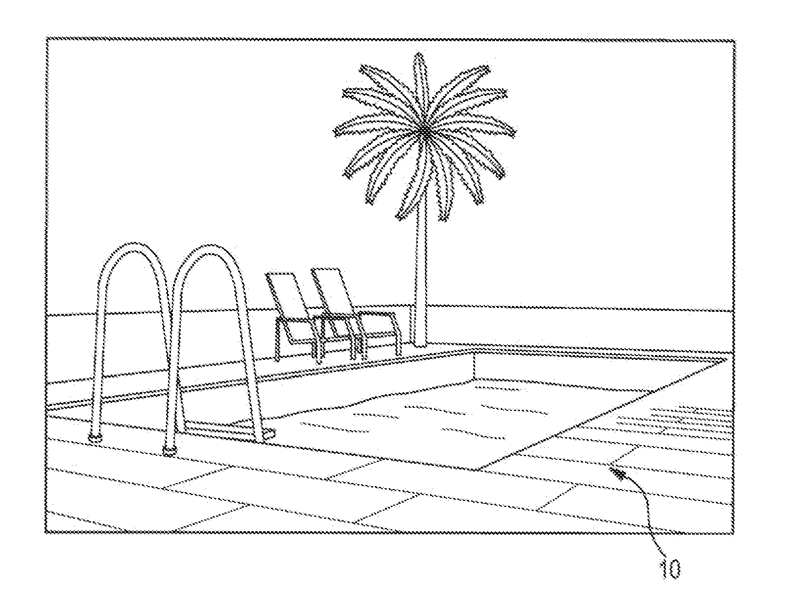
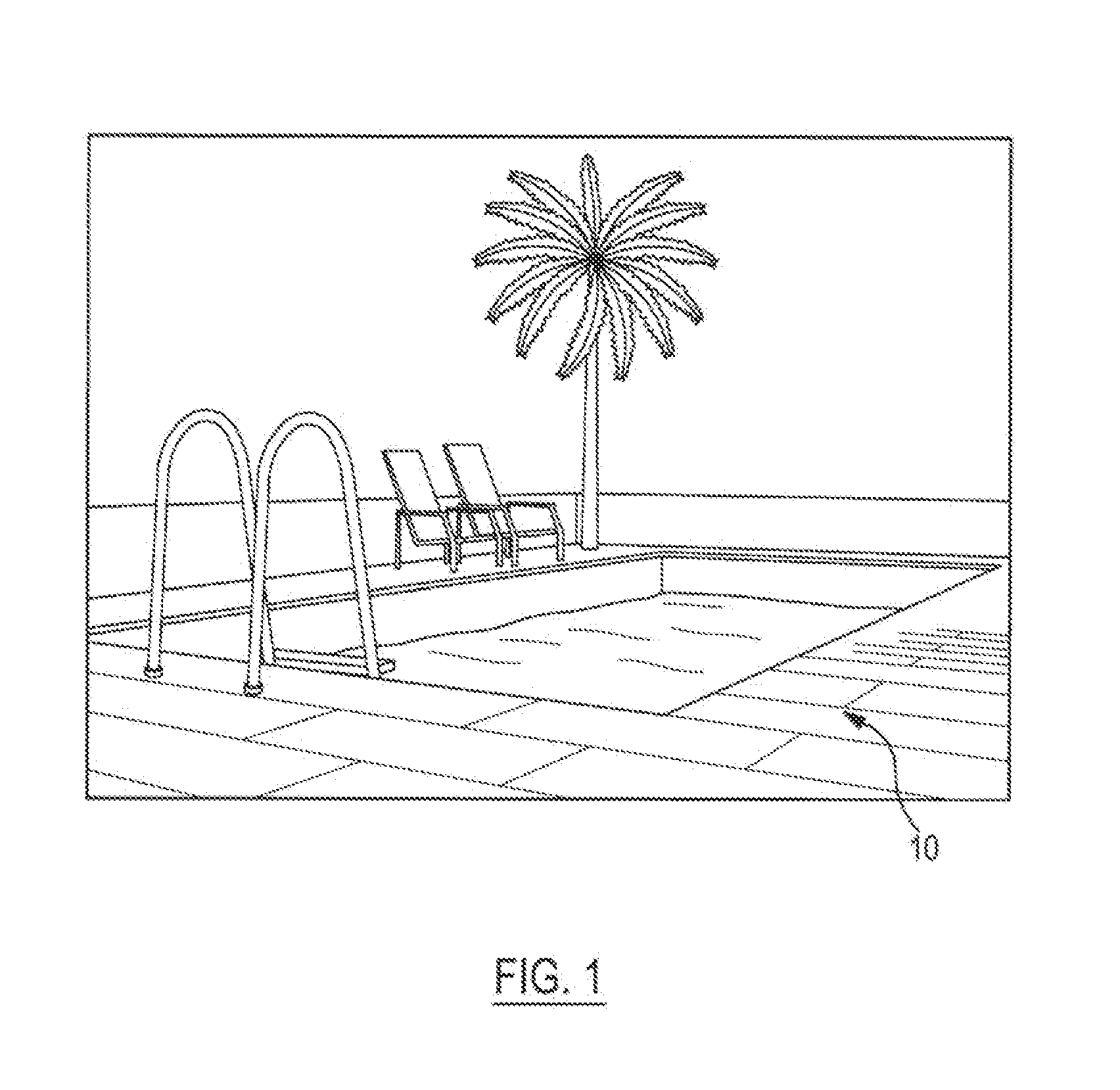
[0044]The invention is a modular, fluid thermal transfer device made up of a thermal panel which may be, but is not limited to a standard two feet by two feet architectural concrete paver with a thickness of between one inch and three inches coupled to a powder coated roll bonded heat exchanger. Referring to FIG. 1, there is shown a view of thermal panels 10 here disclosed arranged in rows and columns on a roof top patio of a high rise building where the heat from the sun is absorbed by the panels and is used to heat a fluid.

[0045]The panels can be used to collect solar heat energy when placed on balconies, terraces, low sloping roofs, plazas, sidewalks, patios, roof top patios, and pool patios. The collected energy can be used to heat domestic water, pool water, stored water for future heating and heat pumps. The removal of the heat from the paver surface will help to cool the surface making for a more comfortable and usable environment.

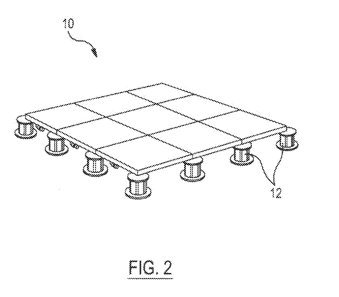
[0046]Referring to FIG. 2, there is shown a p...


PUM


Abstract

A modular thermal panel comprising a paver having a top and bottom surface, and a heat exchanger having connected top and bottom panels with channels formed there between for receiving a heat exchange fluid. The top panel of the heat exchanger is coupled to the bottom surface of the thermal mass unit, an insulator panel is coupled to the bottom panel of the heat exchanger, and inlet and outlet tubes are coupled to the heat exchanger for feeding heat exchange fluid to and from the heat exchanger. The size of the heat exchanger is substantially equal to the size of the paver and the edges of the heat exchanger are substantially aligned with the edges of the paver. The heat exchanger is made of thermally transmissive material including polymers, stainless steel, aluminum, or copper and the thermal mass unit is made of a material which includes modular or pre-formed or formed in place concrete, cement, gypsum concrete, or stone.

Description

BACKGROUND OF THE INVENTION[0001]1. Field of the Invention[0002]The present invention relates to apparatus for the transfer of thermal energy between a thermal mass object and a fluid contained and transited within a heat exchanger and, more specifically, to a modular thermal panel that can be easily connected and disconnected to other modular thermal panels to form an array of modular thermal panels which can be used to transfer solar generated heat on a flat surface such as a roof top patio to heat domestic water or as a patio around a pool to heat the pool while concurrently, cooling the patio surface, or to transfer heat into the patio for the purpose of melting snow and ice on the surface.[0003]2. Background of the Invention[0004]The transfer of thermal energy between thermal mass objects such as concrete or stone, and fluid transited within tubes is now well known within the art. This system is often used for radiant heating. Alternately, when heat is transferred from a therma...

Claims


Application Information

Patent Timeline
IPC IPC(8): F28D15/00
CPCE04B9/0421E04B9/0464E04C2/525Y02E10/44Y02B10/20F24J2/0438F24D3/16F24D13/02F24D2200/02F24D2200/08F24D2200/14Y02B10/70F24S20/64Y02B30/00Y02E10/40F28F2210/02
Inventor BARMORE, ROBERT P.
Owner THERMA HEXX
Learn More