Self-testing and self-calibrating fire sprinkler system, method of installation and method of use

Inactive Publication Date: 2012-11-29
W S DARLEY & CO
View PDF9 Cites 36 Cited by
  • Summary
  • Abstract
  • Description
  • Claims
  • Application Information

AI Technical Summary

Benefits of technology

[0014]The present invention aims to supplement and re-tool existing water supplies in residential systems with the ultimate objective being to meet the NPFA 13D promulgated standards. The system is designed to be easy to install and automatically calibrate (se

Problems solved by technology

All commercially known systems, however, are lacking in the way in which they are calibrated to the residential sprinkler system, and in the method in which they are, or should be, tested.
The pump of a system which sits unt

Method used


Image

  • Self-testing and self-calibrating fire sprinkler system, method of installation and method of use
  • Self-testing and self-calibrating fire sprinkler system, method of installation and method of use
  • Self-testing and self-calibrating fire sprinkler system, method of installation and method of use

Examples


Embodiment Construction

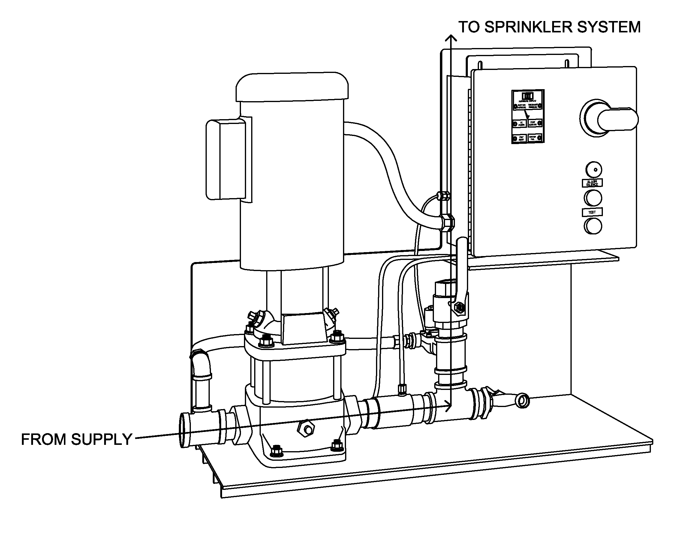
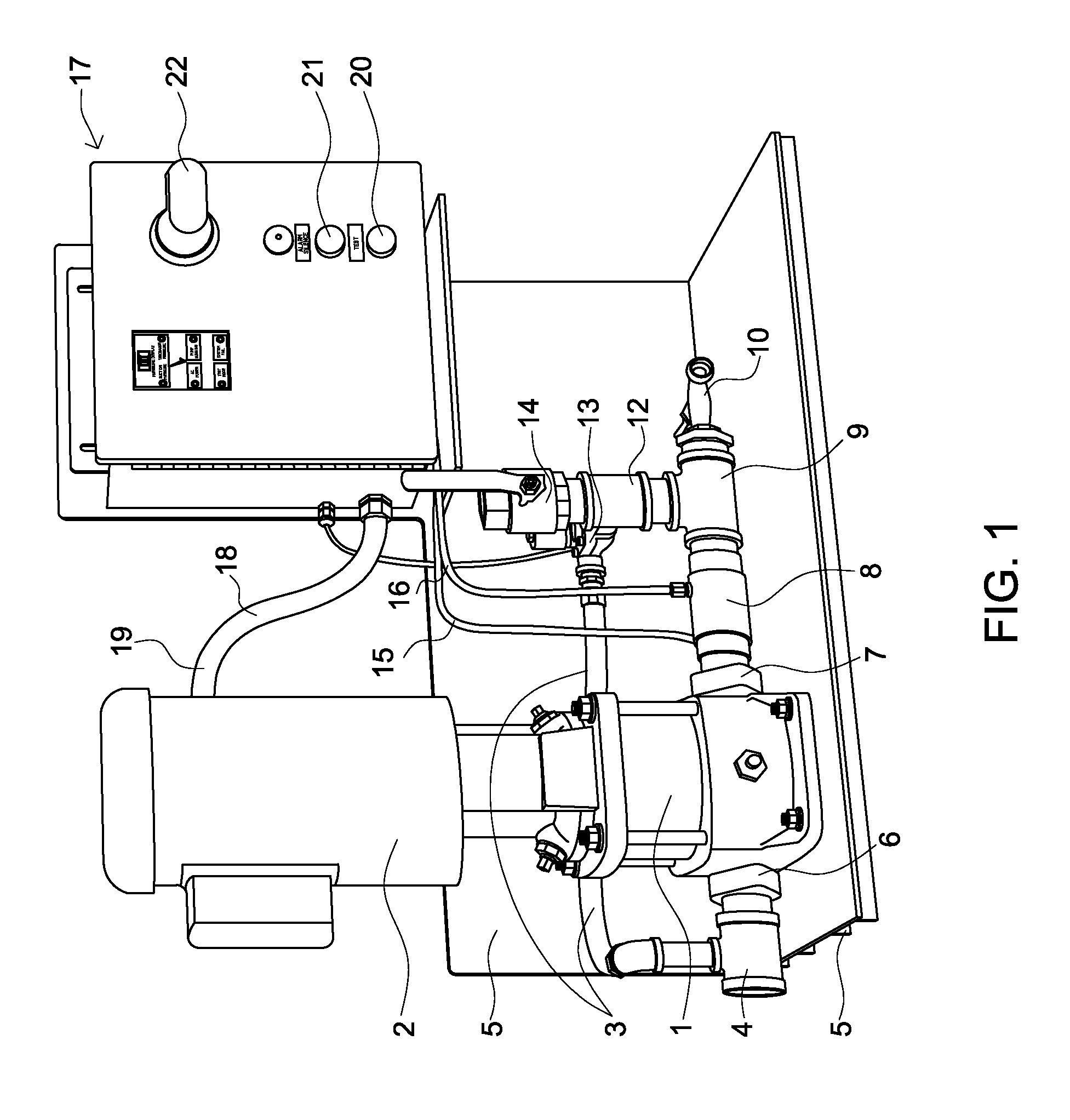
[0024]The system of the present invention is primarily designed to service the residential fire sprinkler market. The system, as depicted in FIG. 1, comprises the following elements: a pump (1), an electric motor (2) engaged to the pump, a controller assembly (17), a solenoid test valve (13), and a manifold assembled out of, and comprising, standard pipe fittings. In the preferred embodiment, the elements of the present invention are all assembled and supported by a custom fabricated Acrylonitrile Butadiene Styrene (ABS) base (5). Elements of the present invention can be used as stand alone elements as well. For instance, a user who already owns a pump and motor could install the controller assembly, solenoid test valve and manifold, as opposed to every element in the preferred embodiment. The base (5) in particular is not a required function of the system, just an added feature for installers and home owners who would prefer to purchase all elements as a package.

[0025]The system ca...


PUM

PropertyMeasurementUnit
Timeaaaaaaaaaa
Timeaaaaaaaaaa
Pressureaaaaaaaaaa

Abstract

A Self-Testing and Self-Setting residential fire pump system for residential fire protection. The system is designed to boost pressure into a residential sprinkler system when water supply is insufficient to meet the sprinkler system's design requirements. The system comprises an in-line vertical multi-stage, centrifugal pump connected to an electric motor with horsepower ranges from ¾ to 10, a flow rate range of 15 gpm-200 gpm, and pressure ranges of 20 psi-238 psi. The system also comprises a controller assembly which is programmed to Self-Test and Self-Calibrate to most residential fire sprinkler systems with the push of a button, and a manifold made from brass or stainless steel pipe fittings connected to the pump's suction and discharge ports, allowing water to flow from an existing water supply through the pump to either the test loop or existing residential fire sprinkler system. The pump and controller can be mounted on an ABS base.

Description

CROSS-REFERENCE TO RELATED APPLICATIONS[0001]I hereby claim the benefit under Title 35, United States Code Section 119(e) of any United States Provisional Application(s) listed below:[0002]Provisional Patent Application No. 61 / 462,027[0003]Filing Date Jan. 27, 2011STATEMENT REGARDING FEDERALLY SPONSORED RESEARCH AND DEVELOPMENT[0004]Non-applicableTHE NAMES OF THE PARTIES TO A JOINT RESEARCH AGREEMENT[0005]Non-applicableINCORPORATION-BY-REFERENCE OF MATERIAL SUBMITTED ON A COMPACT DISC[0006]Non-applicableBACKGROUND OF THE INVENTION[0007]1. Technical Field of the Invention[0008]The present invention relates generally to water supplying systems where pressure switch settings are required, more specifically to fire sprinkler systems, and even more specifically to self-calibrating, self-testing, residential fire sprinkler systems.[0009]2. Background of the Invention[0010]The following description of the art related to the present invention refers to a number of publications and reference...

Claims


Application Information

Patent Timeline
IPC IPC(8): A62C35/64G01L27/00A62C37/50
CPCA62C37/50A62C35/64
Inventor TAYLOR, JEREMY
Owner W S DARLEY & CO
Why Eureka
Try Eureka