Paper feeder and image forming apparatus including the same

Active Publication Date: 2012-11-29
SHARP KK
View PDF5 Cites 19 Cited by
  • Summary
  • Abstract
  • Description
  • Claims
  • Application Information

AI Technical Summary

Benefits of technology

[0023]The image forming apparatus of the present invention includes the above-described paper feeder of the present invention. Such an imag

Problems solved by technology

At this time, the amount of air exhausted through the exhaust duct also reduces, and the exhausted air cannot be utilized.
For example, in the case where exhausted air is blown through the exhaust duct a

Method used


Image

  • Paper feeder and image forming apparatus including the same
  • Paper feeder and image forming apparatus including the same
  • Paper feeder and image forming apparatus including the same

Examples


Embodiment Construction

[0065]An embodiment of the present invention will be hereinafter described in detail with reference to the accompanying drawings.

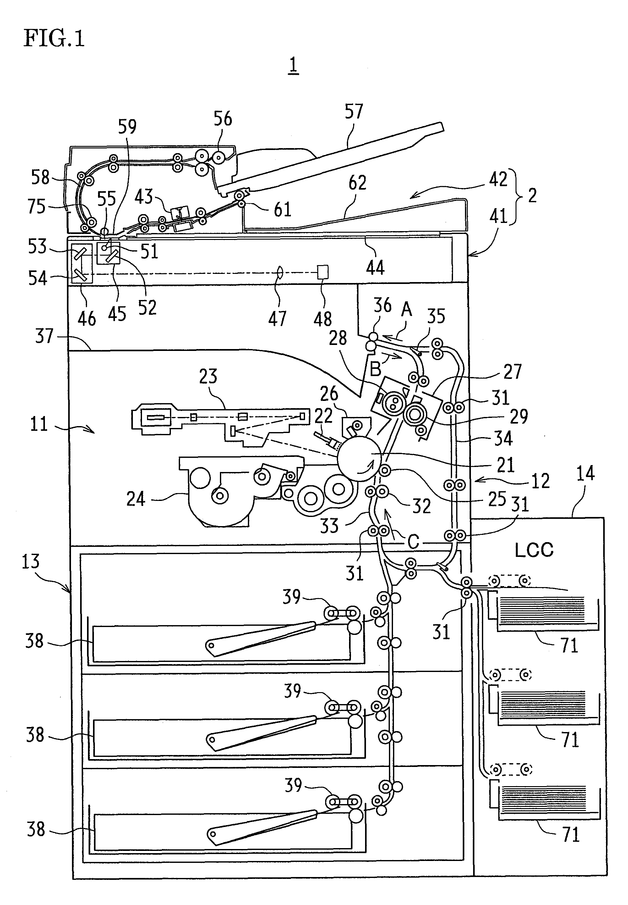
[0066]FIG. 1 is a cross-sectional view of an image forming apparatus to which one embodiment of a paper feeder of the present invention is applied. This image forming apparatus 1 is designed to print a monochrome image represented by image data on a recording paper, and its configuration is roughly divided into an original reader 2, a printing unit 11, a paper transport unit 12, a paper supply unit 13, and a large capacity cassette (LCC) 14.

[0067]This image forming apparatus 1 generates image data by reading an original image with the original reader 2, or acquires image data by receiving image data input from an external terminal apparatus or the like, performs various types of image processing on the image data, and then prints the image represented by the image data on a recording paper with the printing unit 11.

[0068]A photosensitive drum 21 is arrange...


PUM


Abstract

In a paper feeder, an air hole that allows air to pass through is formed on a paper transport belt, a fan for breathing and exhausting air and an exhaust duct having an opening for exhausting air. Air is exhausted from the fan through the exhaust duct, the fan and an air intake duct for breathing air are connected to each other, and air is breathed from the air hole through the air intake duct towards the fan. This paper feeder includes: an air state detection unit for detecting at least one of an air pressure and an air flow rate in the air intake duct; an opening and closing unit provided to the air intake duct for opening and closing the opening; and a control unit for opening and closing the opening based on a result of detection by the air state detection unit.

Description

BACKGROUND OF THE INVENTION[0001]This application claims priority under 35 U.S.C. §119(a) on Patent Application No. 2011-115890 filed in Japan on May 24, 2011, the entire contents of which are herein incorporated by reference.BACKGROUND OF THE INVENTION[0002]1. Field of the Invention[0003]The present invention relates to a paper feeder for pulling out and sending papers from a bundle of papers loaded on a paper tray, and an image forming apparatus including this paper feeder.[0004]2. Description of the Related Art[0005]An example of this kind of paper feeders is disclosed in JP H6-1467 (hereinafter referred to as Patent Literature 1). Here, a paper transport belt is arranged above the paper tray, air is breathed from an air hole on the paper transport belt through an air intake duct towards a fan, and papers in a bundle of papers on the paper tray is attached to the paper transport belt and thus transported. The air exhausted by the same fan is blown through an exhaust duct against ...

Claims


Application Information

Patent Timeline
IPC IPC(8): B65H3/08
CPCB65H1/14B65H3/128B65H2801/06B65H2515/342B65H2515/212B65H2511/212B65H2406/41B65H2406/3662B65H3/48B65H7/16B65H2405/15B65H2406/364B65H2220/02B65H2220/11B65H2220/01B65H2515/20B65H2515/34
Inventor FUJITA, MASAHIKOKIMURA, MASAHARUFUKADA, YASUAKIHASHIMOTO, SUSUMU
Owner SHARP KK
Why Eureka
Try Eureka