Supercharge Your Innovation With Domain-Expert AI Agents!

Self generating power source

a self-generating, power source technology, applied in the direction of electric generator control, machines/engines, transportation and packaging, etc., can solve the problems of poor power generation performance, and achieve the effect of enhancing convenience during us

Inactive Publication Date: 2012-11-29
TAIMAG CORP
View PDF0 Cites 6 Cited by
  • Summary
  • Abstract
  • Description
  • Claims
  • Application Information

AI Technical Summary

Benefits of technology

[0007]Therefore, the object of the present invention is to provide a self generating power source that can eliminate the aforesaid drawback of the prior art.
[0011]The advantages and effects of the present invention lie in that: magnetic attraction between adjacent ones of the first induction members of an adjacent series connected pair of the self generating power source is avoided, such that the range of relative movement between the first and second induction members or between the magnet set and the coil member of a self generating power source is not limited by another, adjacent self generating power source. Moreover, when the self generating power source runs out of electricity, it does not need to be removed for individual manipulation, but can be shook together with other self generating power sources when multiple ones of the self generating power sources are connected in series inside an electronic device, thereby enhancing convenience during use.

Problems solved by technology

However, while many portable electronic devices, such as flash lights, portable stereos, etc., use multiple series-connected batteries as their power sources, when the conventional self generating batteries 1 are used in series, adjacent ones of the induction members 12 of an adjacent pair of the conventional self generating batteries 1 are magnetically attracted to each other since adjacent magnetic poles of the adjacent induction members 12 are of opposite polarity, such that the range of movement of the induction member 12 relative to the coil unit 13 of one conventional self generating battery 1 is limited by the other conventional self generating battery 1, thereby resulting in poor power generating performance.
Consequently, in order to obtain better power generating performance, it is necessary to take the conventional self generating batteries 1 out of the portable electronic devices, and shake the conventional self generating batteries 1 individually, which is inconvenient.

Method used


Image

  • Self generating power source
  • Self generating power source
  • Self generating power source

Examples


Embodiment Construction

[0019]Before the present invention is described in greater detail, it should be noted that like elements are denoted by the same reference numerals throughout the disclosure.

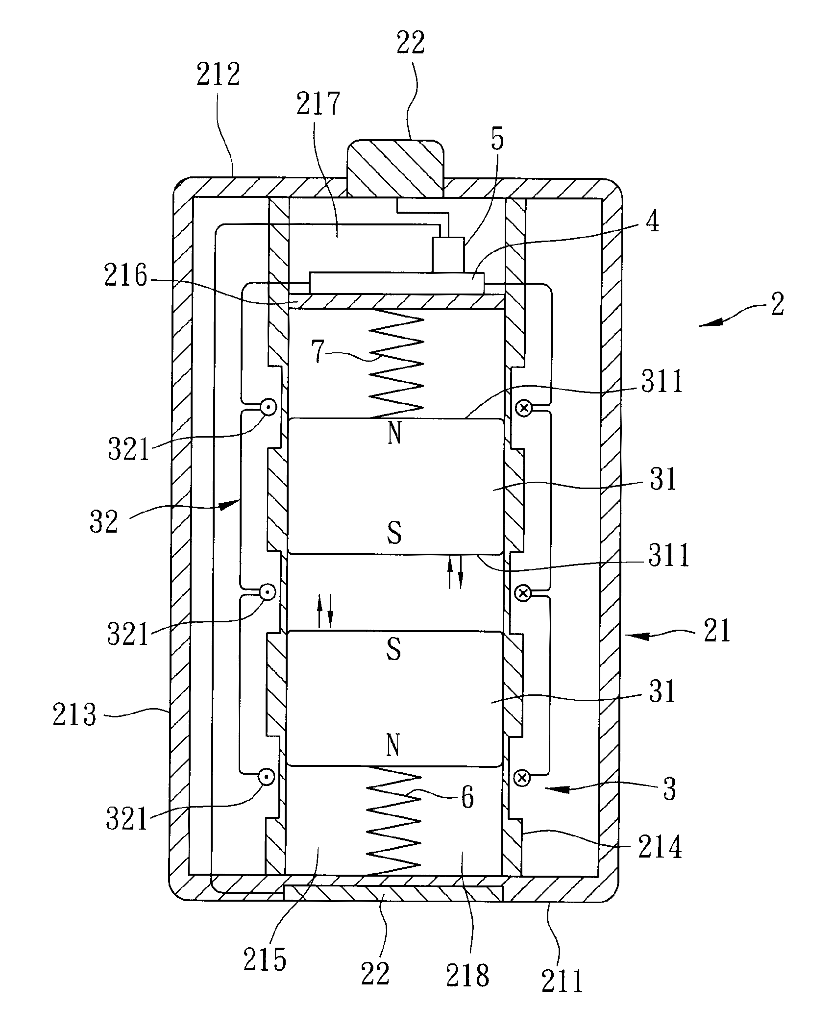
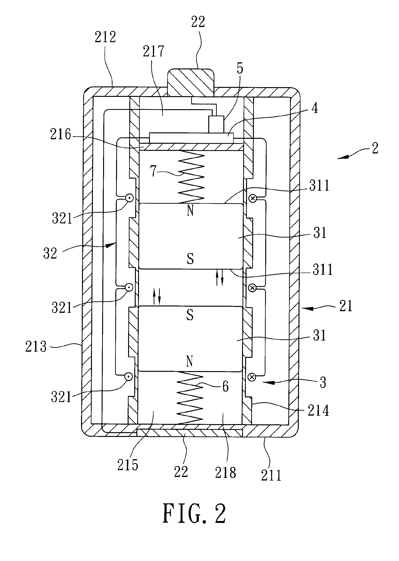
[0020]With reference to FIG. 2, the first preferred embodiment of a self generating power source according to the present invention includes a housing unit 2, an energy conversion unit 3, a rectifying unit 4, and an energy storage unit 5.

[0021]The housing unit 2 includes a housing body 21. The energy conversion unit 3 is disposed inside the housing body 21, and includes two first induction members 31 and a second induction member 32. The first induction members 31 are movable relative to the second induction member 32 so as to generate an alternating current in the second induction member 32 by virtue of electromagnetic induction. Each of the first induction members 31 has two magnetic poles 311 that are opposite to each other in polarity (N, S). The first induction members 31 are disposed such that two of the m...


PUM


Abstract

A self generating power source includes a housing unit including a housing body, and an energy conversion unit, a rectifying unit and an energy storage unit all disposed inside the housing body. The energy conversion unit includes two first induction members and a second induction member. The first induction members are movable relative to the second induction member for generating an alternating current in the second induction member by virtue of electromagnetic induction. Each first induction member has two magnetic poles opposite to each other in polarity. The first induction members are disposed such that two of the magnetic poles of the first induction members having the same polarity are disposed to confront each other. The rectifying unit is coupled electrically to the second induction member for converting the alternating current into a direct current. The energy storage unit is coupled electrically to the rectifying unit for storing the direct current.

Description

BACKGROUND OF THE INVENTION[0001]1. Field of the Invention[0002]The invention relates to a power source, more particularly to a self generating power source.[0003]2. Description of the Related Art[0004]With reference to FIG. 1, Taiwanese Utility Model Publication No. M319580 entitled “self generating battery” discloses a conventional self generating battery 1 that includes a tubular housing 11, an induction member 12, a coil unit 13 and an energy storage unit 14.[0005]The induction member 12 has two magnetic poles that are opposite to each other in polarity, and is movably or slidably disposed in the tubular housing 11. The coil unit 13 is disposed on the outer peripheral surface of the tubular housing 11. The energy storage unit 14 is connected electrically to the coil unit 13. By shaking the self generating battery 1, the induction member 12 slides relative to the coil unit 13 so as to generate electrical energy.[0006]However, while many portable electronic devices, such as flash ...

Claims


Application Information

Patent Timeline
IPC IPC(8): F03G7/08
CPCH02K35/02
Inventor CHAN, FU-HOCHEN, PIN-HUNGLU, WEN-LONGCHENG, KUO-TUNG
Owner TAIMAG CORP
Features
  • R&D
  • Intellectual Property
  • Life Sciences
  • Materials
  • Tech Scout
  • Unparalleled Data Quality
  • Higher Quality Content
  • 60% Fewer Hallucinations
Learn More