Check patentability & draft patents in minutes with Patsnap Eureka AI!

Input power measuring device

a technology of input power and measuring device, which is applied in the direction of ac/dc measuring bridge, reference comparison, instruments, etc., can solve the problems of difficulty in measuring the input power of an ssd inserted into a dual inline memory module, and the socket in the motherboard

Inactive Publication Date: 2012-11-29
WARECONN TECH SERVICE (TIANJIN) CO LTD
View PDF3 Cites 6 Cited by
  • Summary
  • Abstract
  • Description
  • Claims
  • Application Information

AI Technical Summary

Benefits of technology

The present patent relates to an input power measuring device for solid state drives (SSDs) that can measure the input power of the SSDs accurately. The device includes a measuring circuit with a resistor, differential amplifier circuit, voltage dividing circuit, controller, and display screen. The device is designed to be easily mounted on a motherboard and can measure the input power of the SSDs during operation. The technical effect of the patent is to provide a reliable and accurate method for measuring the input power of SSDs, which can help to ensure the reliability of the SSDs and the data they store.

Problems solved by technology

However, it is difficult to measure the input power of an SSD inserted into a dual inline memory module (DIMM) socket in a motherboard.

Method used


Image

  • Input power measuring device
  • Input power measuring device
  • Input power measuring device

Examples


Embodiment Construction

[0009]The disclosure, including the accompanying drawings in which like references indicate similar elements, is illustrated by way of example and not by way of limitation. It should be noted that references to “an” or “one” embodiment in this disclosure are not necessarily to the same embodiment, and such references mean at least one.

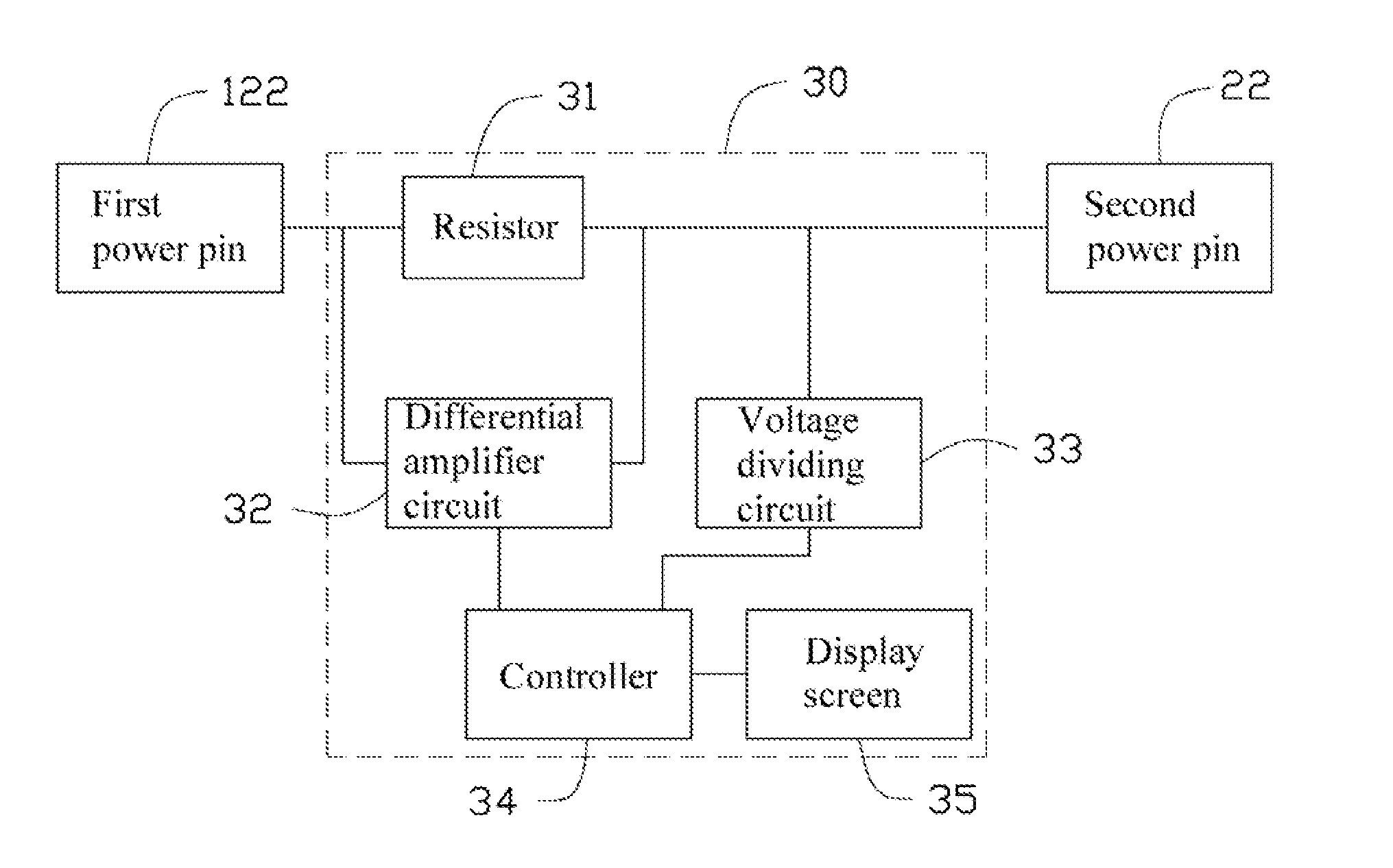
[0010]Referring to the FIGS. 1-3, an embodiment of an input power measuring device 100 is used to measure an input power of a solid state drive (SSD) 200. The input power measuring device 100 includes a board 10, a dual inline memory modules (DIMM) socket 20 mounted on a top side of the board 10, and a measuring circuit 30 arranged on the board 10. Two latching slots 14 are defined in two opposite ends of the board 10. The latching slots 14 are used to engage with two latching blocks of a DIMM socket 320 mounted on a motherboard 300, thereby fixing the input power measuring device 100 to the DIMM socket 320. An edge connector 12 is formed on a bottom s...


PUM


Abstract

An input power measuring device includes a board with an edge connector, a first dual inline memory modules (DIMM) socket, a resistor, a differential amplifier circuit, a voltage dividing circuit, a display screen, and a controller. When the edge connector is inserted into a second DIMM socket of a motherboard and the motherboard is powered on, the resistor samples first current, and converts the first current into a first voltage. The differential amplifier circuit amplifiers the first current to a second current. The voltage dividing circuit divides the first voltage, and outputs a second voltage. The controller converts the second current into a third current, converts the second voltage into a third voltage, and calculates a power according to the third current and the third voltage.

Description

BACKGROUND [0001]1. Technical Field[0002]The present disclosure relates to an input power measuring device.[0003]2. Description of Related Art[0004]With the development of flash memories (e.g., NAND memories), some attempts have been made to use these flash memories as data storage devices. One form of the data storage devices using NAND flash memories is referred as solid state drives (SSDs). In order to ensure reliability of the SSDs, a measurement for the input power of the SSDs is required. However, it is difficult to measure the input power of an SSD inserted into a dual inline memory module (DIMM) socket in a motherboard. Therefore, there is room for improvement in the art.BRIEF DESCRIPTION OF THE DRAWINGS [0005]Many aspects of the present embodiments can be better understood with reference to the following drawings. The components in the drawings are not necessarily drawn to scale, the emphasis instead being placed upon clearly illustrating the principles of the present embod...

Claims


Application Information

Patent Timeline
Patent Type & Authority Applications(United States)
IPC IPC(8): G01R19/00
CPCG11B2220/60G06F1/28G06F1/185G11C2029/5602G11C29/50G11C2029/5002G11C2029/5006G11C5/04
Inventor BAI, YUNYANG, FU-SENTONG, SONG-LIN
Owner WARECONN TECH SERVICE (TIANJIN) CO LTD
Features
  • R&D
  • Intellectual Property
  • Life Sciences
  • Materials
  • Tech Scout
  • Unparalleled Data Quality
  • Higher Quality Content
  • 60% Fewer Hallucinations
Learn More