Data bus

a data bus and data technology, applied in the direction of logic circuit coupling/interface arrangement, pulse technique, instruments, etc., can solve the problems of impedance mismatch during read, distortion of the waveform of the read data signal, and difficulty in well balancing impedance matching between signal transfer in one direction and transfer in the other direction, so as to achieve high-reliability data transfer

Inactive Publication Date: 2005-01-18
RENESAS ELECTRONICS CORP
View PDF6 Cites 66 Cited by
  • Summary
  • Abstract
  • Description
  • Claims
  • Application Information

AI Technical Summary

Benefits of technology

[0018]In a data bus bidirectionally transferring data, an object of the present invention is to provid

Problems solved by technology

When signal lines bidirectionally transfer data, as the data bus 12 shown in the example above, and especially when the transferred signals have higher frequencies, it is difficult to well balance impedance matching during signal transfer in one direction and impedance matching during transfer in the other direction.
For example, when the impedance of each terminating resistor is set to

Method used


Image

  • Data bus
  • Data bus
  • Data bus

Examples


Embodiment Construction

am showing the structure of a memory system according to a fifth preferred embodiment;

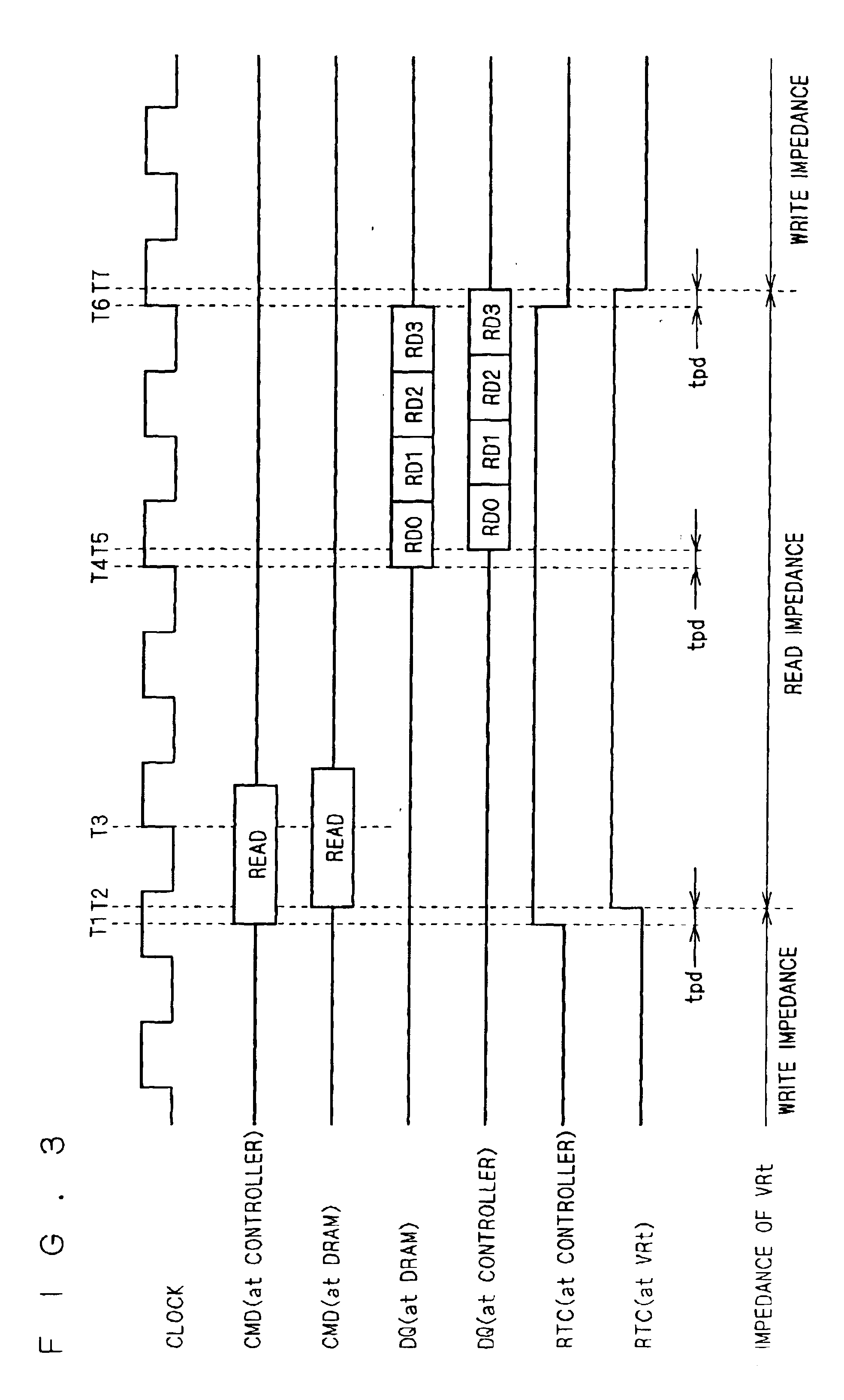
[0031]FIG. 9 is a timing chart showing an example of operation of the memory system of the fifth preferred embodiment;

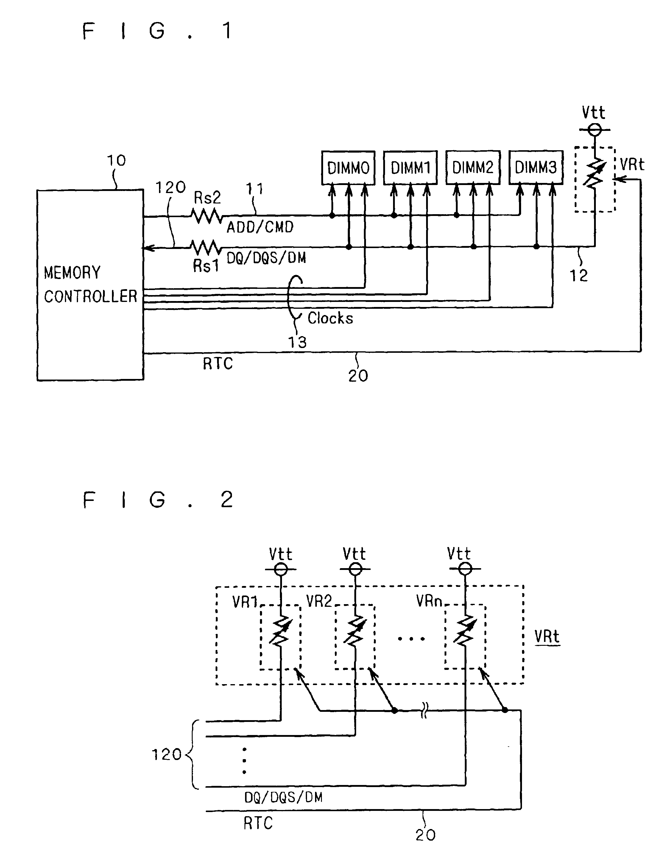
[0032]FIG. 10 is a diagram showing an example of the structure of the terminating variable resistors in a memory system according to a sixth preferred embodiment;

[0033]FIGS. 11 and 12 are diagrams showing the structure of a memory system according to a seventh preferred embodiment;

[0034]FIGS. 13 and 14 are diagrams each showing the structure of a memory system according to an eighth preferred embodiment; and

[0035]FIGS. 15 and 16 are diagrams each showing the structure of a conventional memory system.

DESCRIPTION OF THE PREFERRED EMBODIMENTS

[0036]

[0037]FIG. 1 is a diagram showing the structure of a memory system to which a data bus of a first preferred embodiment of the invention can be applied. In this diagram, the same components as those shown in FIG. 15 are denoted by the same ref...


PUM


Abstract

In a memory system having a data bus transferring data in either direction, highly reliable data transfer is provided regardless of the direction in which data is transferred. The signal lines of a data bus (12) bidirectionally transfer data. That is to say, during data write operations to a DIMM, the signal lines transfer data from a memory controller (10) to the DIMM, and during data read operations, they transfer data from the DIMM to the memory controller (10). The signal lines have, as terminating resistors, terminating variable resistors (VRt) whose impedance is controlled by the memory controller (10). During data write operations to the DIMM, the memory controller (10) sets the impedance of each terminating variable resistor (VRt) at a value suitable for writing, and during data read operations, it sets the impedance of each terminating variable resistor (VRt) at a value suitable for reading.

Description

BACKGROUND OF THE INVENTION[0002]1. Field of the Invention[0003]The present invention relates to a technique for transmitting / receiving data using a data bus.[0004]2. Description of the Background Art[0005]FIGS. 15 and 16 are diagrams each showing the structure of a conventional memory system constructed on a motherboard of a computer system. The diagrams show examples of a memory system that includes four DIMMs (Dual Inline Memory Modules) having DRAMs (Dynamic Random Access Memories). As shown in the diagrams, the four DIMMs (DIMM 0 to DIMM 3) and a memory controller 10 are connected through an address / command bus 11, a data bus 12, and clock lines 13.[0006]Through the address / command bus 11 and the data bus 12, the memory controller 10 controls operations of the four DIMMs and also reads / writes data from / to the DIMMs. The address / command bus 11 transfers command signals (CMD) and address signals (ADD) from the memory controller 10 to the individual DIMMs. The command signals (CMD...

Claims


Application Information

Patent Timeline
IPC IPC(8): G11C7/10G06F3/00G06F12/00G06F13/16G11C11/409H03K19/0175
CPCG11C7/10
Inventor YAMAGATA, TADATO
Owner RENESAS ELECTRONICS CORP
Why Eureka
Try Eureka