Method for Manufacturing Lens Unit, Imaging Device, Method for Manufacturing Mold, Mold For Molding, and Method for Molding Glass Lens Array

a lens array and manufacturing method technology, applied in the field of manufacturing lenses, can solve the problems of increasing the number of lenses required by an instrument, and achieve the effect of accurate and convenient mass production of lenses

Inactive Publication Date: 2012-11-29
KONICA MINOLTA OPTO
View PDF3 Cites 6 Cited by
  • Summary
  • Abstract
  • Description
  • Claims
  • Application Information

AI Technical Summary

Benefits of technology

[0028]According to the present invention, it is possible to provide a method for manufacturing a lens unit, an imaging device, a method for manufacturing a mold, a mo...

Problems solved by technology

Further, in imaging lenses to form a subject image on these imaging elements, in response to miniatur...

Method used


Image

  • Method for Manufacturing Lens Unit, Imaging Device, Method for Manufacturing Mold, Mold For Molding, and Method for Molding Glass Lens Array
  • Method for Manufacturing Lens Unit, Imaging Device, Method for Manufacturing Mold, Mold For Molding, and Method for Molding Glass Lens Array
  • Method for Manufacturing Lens Unit, Imaging Device, Method for Manufacturing Mold, Mold For Molding, and Method for Molding Glass Lens Array

Examples


Embodiment Construction

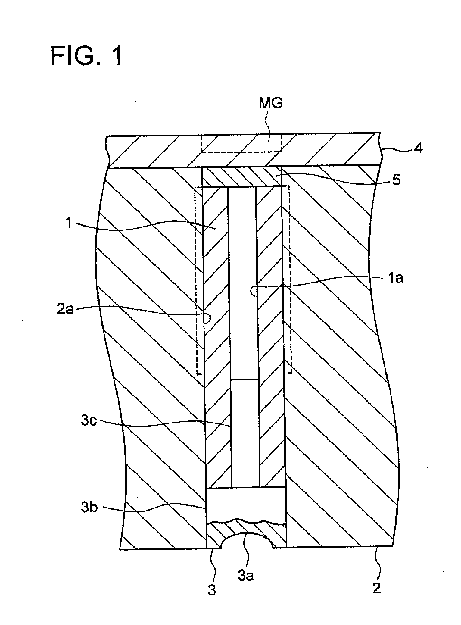
[0050]Hereinafter, preferred embodiments according to the present invention will be described with reference to the drawings. FIG. 1 illustrates a sectional view of a part of an injection mold used for this embodiment. It is to be noted that the up-down direction is defined as the same direction as a vertical direction in FIG. 1.

[0051]As illustrated in FIG. 1, a hollow cylindrical core supporting member 1 is a hollow cylindrical member having equal outer diameter throughout the entire length of it, and includes a through-hole 1a in the axial direction, and the material is composed of STAVAX (pre-hardened steel) which is a magnetic substance. The coefficient of thermal expansion of STAVAX is 1.2×10⁻⁵ / K.

[0052]Meanwhile, a mold sleeve 2 includes a cylindrical aperture 2a Inside the aperture 2a, the core supporting member 1 is engaged. A core 3, which is made of a ceramic, includes a head section 3b having a molding transfer surface 3a formed on an end face, and a shaft section 3c which...


PUM

PropertyMeasurementUnit
Forceaaaaaaaaaa
Diameteraaaaaaaaaa
Distanceaaaaaaaaaa

Abstract

A method for manufacturing a lens unit including the steps of: forming a first lens array, having plural first lens sections and first reference surfaces formed in a predetermined arrangement, via glass forming by arranging a glass material between a first assembled molds and by clamping the molds; forming a second lens array, having plural second lens sections and second reference surfaces formed in a predetermined arrangement, via glass forming by arranging a glass material between a second assembled molds and by clamping the molds; forming a third lens array by stacking and bonding the first and second lens arrays so that an optical axis of each lens section of the first and second lens arrays coincide, by using the first and second reference surfaces; and cutting the third lens array into each lens unit which includes at least each one of the first and the second lens sections.

Description

TECHNICAL FIELD[0001]The present invention relates to a method for manufacturing a lens unit, an imaging device, a method for manufacturing a mold, a mold for molding, and a method for molding a glass lens array.BACKGROUND TECHNOLOGY[0002]A compact and extremely thin imaging device (hereinafter, referred to also as a “camera module”) is being used for portable terminals such as mobile phones and PDA (Persona Digital Assistant) which are compact and thin electronic devices. As image sensors used in these imaging devices, solid-state imaging elements such as CCD-type image sensors and CMOS-type image sensors are known. Over recent years, the increase of pixels in imaging elements has progressed, and resolution and performance have been enhanced. Further, in imaging lenses to form a subject image on these imaging elements, in response to miniaturization of imaging elements, compactness is being required, and this requirement tends to grow year by year.[0003]As such an imaging lens used...

Claims


Application Information

Patent Timeline
IPC IPC(8): C03B19/00C03C27/10B32B38/04C03B7/14G02B7/02B32B37/24
CPCC03B11/082C03B23/22C03B2215/414G02B3/0006C03B2215/80G02B7/025C03B2215/76
Inventor MATSUDA, HIROYUKIIBI, TAKASHIIWAIDA, KENICHIHAYAMIZU, SHUNICHI
Owner KONICA MINOLTA OPTO
Why Eureka
Try Eureka