Method and base station for transmitting downstream link data, and method and user device for receiving downstream link data

a downstream link and data transmission technology, applied in the field of wireless communication systems, can solve problems such as deterioration of overall system throughput, achieve the effects of reducing the time required for switching the transmission/reception (tx/rx) mode of user equipment (ue), reducing the time required for switching the transmission/reception mode, and reducing the time required for demodulating user data transmitted

Active Publication Date: 2012-11-29
LG ELECTRONICS INC
View PDF4 Cites 104 Cited by
  • Summary
  • Abstract
  • Description
  • Claims
  • Application Information

AI Technical Summary

Benefits of technology

[0028]As is apparent from the above description, exemplary embodiments of the present invention have the following effects.
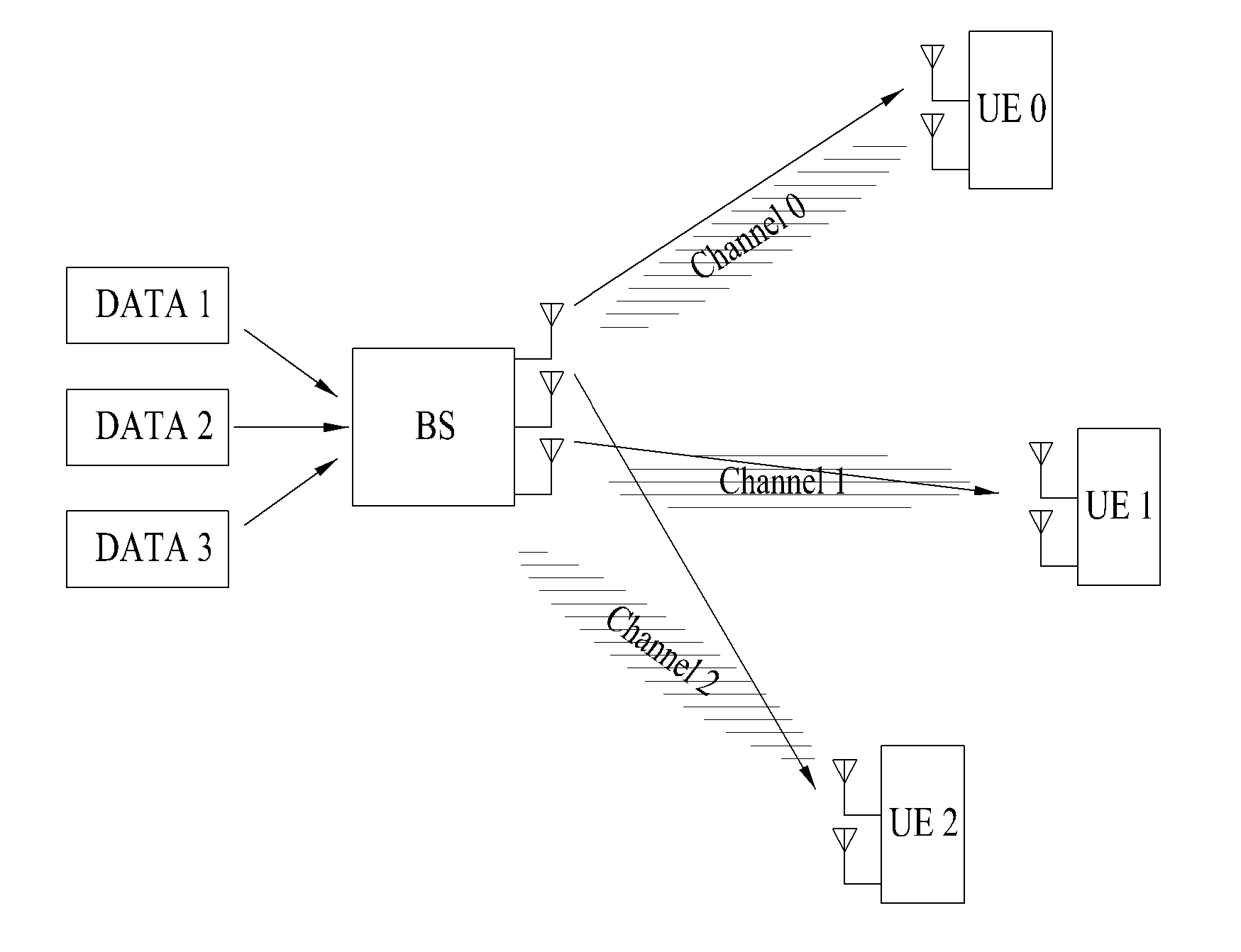
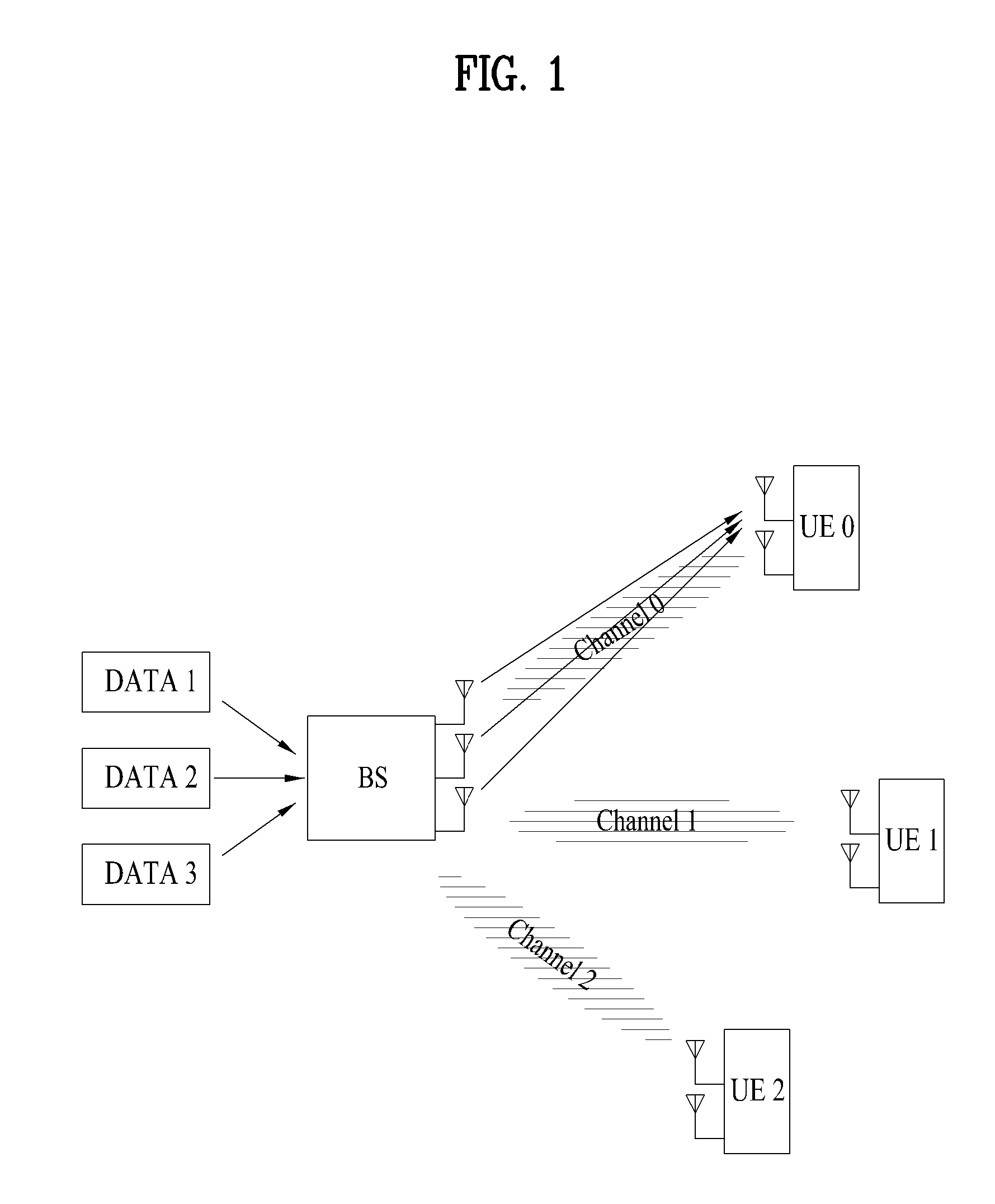
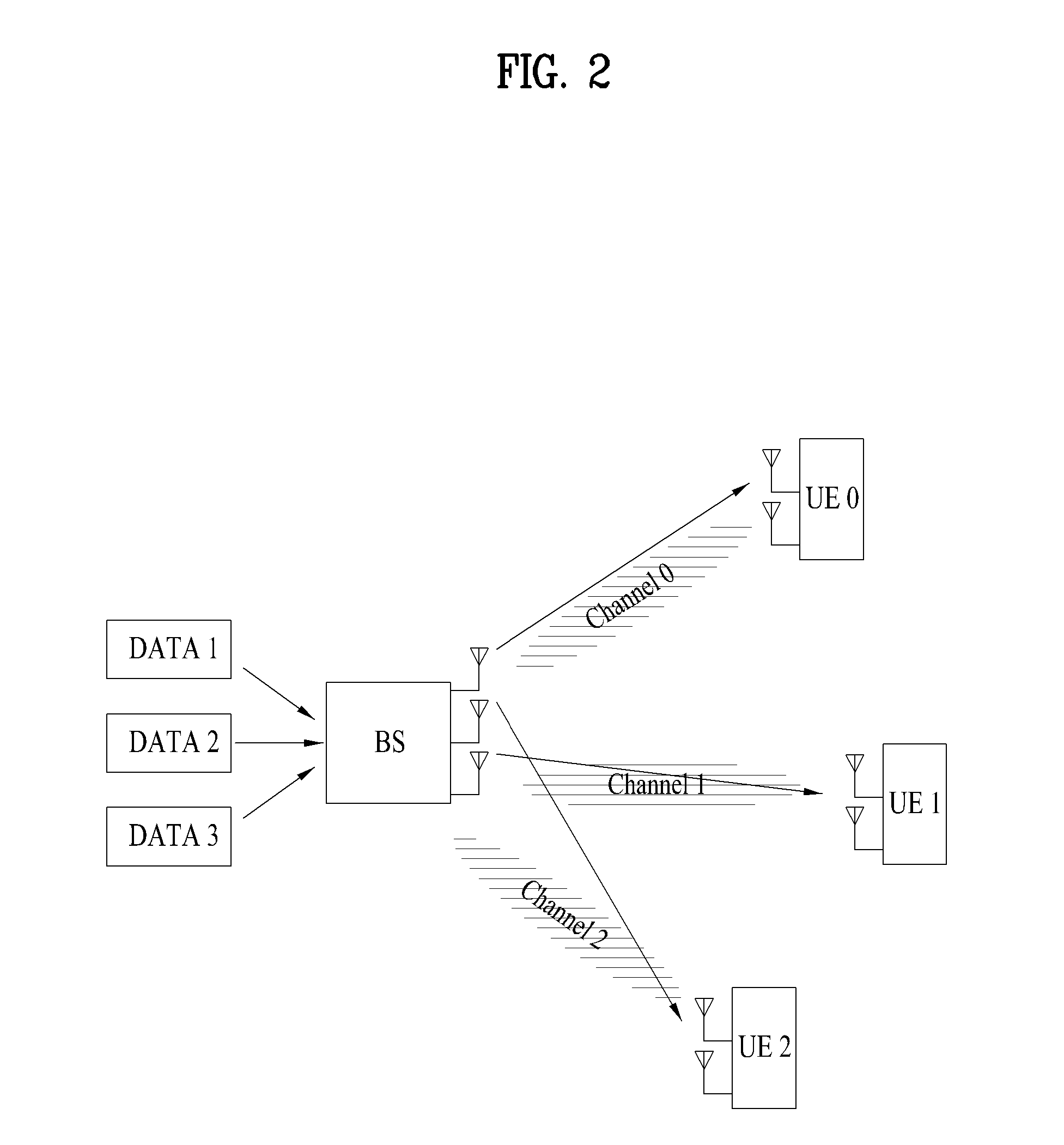
[0029]In accordance with the embodiments of the present invention, although a MIMO transmission mode is not changed, a user equipment (UE) can receive SU-MIMO transmission data and MU-MIMO transmission data. As a result, a time required for switching a transmission/reception (Tx/Rx) mode of the user equipment (UE) is reduced, resulting in an increase in overall system throughput.
[0030]In accordance with the present invention, the user equipment (UE) can efficiently demodulate user data transmitted to the user equipment (UE).
[0031]The base station (BS) according to th

Problems solved by technology

In order to perform transmission mode switching between the SU-MIMO mode and the MU-MIMO mode,

Method used


Image

  • Method and base station for transmitting downstream link data, and method and user device for receiving downstream link data
  • Method and base station for transmitting downstream link data, and method and user device for receiving downstream link data
  • Method and base station for transmitting downstream link data, and method and user device for receiving downstream link data

Examples


embodiment 1-1

Fixed DMRS set is Used Per Rank

[0123]The DMRS set may be predefined according to the number (i.e., rank) of layers allocated to the UE. For example, in the case of Rank-3 transmission, DMRSs corresponding to layers from Layer-0 to Layer-2 may be utilized in Table 1. If the mapping relationship of Type-1 is achieved between layers and DMRSs, DMRSs of {1C, 2C, 1D} may be adapted to transmit user data for one or more UEs receiving Rank-3 transmission. In so far as a DMRS set used for a specific rank is predefined, other DMRS sets (for example, {1D, 2D, 3D}) may be utilized for Rank-3 transmission.

[0124]Based on signaling from the BS or blind decoding of the UE, the UE can recognize how many layers have been allocated to the UE. Accordingly, according to Embodiment 1-1 in which a DMRS set is fixed per rank, the UE can detect its own DMRS(s) from among DMRSs transmitted from the BS. Moreover, the UE can demodulate UE data transmitted from one or more layers on the basis of the detected D...

embodiment 1-2

Contiguous DMRS(s) Starting from a Specific Layer are Used

[0125]An arbitrary DMRS set may be utilized to transmit the same rank during each transmission time. In this case, information indicating which DMRS set is used is transferred to the UE. For example, not only a rank for the UE but also a start DMRS may be adapted to indicate a DMRS set used for data transmission to the UE. Referring to Type-1 of Table 1, the UE may demodulate data transmitted to the UE using 4 DMRSs (i.e., {1D, 2D, 3C, 4D}) starting from 1D, namely, the UE may demodulate UE data through 4 layers corresponding to 4 DMRSs. In another example, provided that a start DMRS is set to a DMRS corresponding to Layer-6 of Table 1 and a rank is set to 3 (Rank-3), 3 DMRSs may start from 3D in Type-1 and may be cyclically allocated to the UE. That is, the UE may use the allocated DMRSs {3D, 4D, 1C} to demodulate a reception layer.

1-3. Mapping of Layer to DMRS According to Feedback Mode

[0126]The mapping relationship between...


PUM


Abstract

The present invention relates to a method and apparatus which transmit/receive at least one demodulation reference signal by using a CDM group and/or a transmission rank of a user device that have been used to transmit the at least one demodulation reference signal for the user device, an OCC that has been used to spread the demodulation reference signal, etc. Also, the present invention relates to a method and apparatus which change an antenna port for transmitting the demodulation reference signal by using NDI for a disabled transmission block.

Description

FIELD OF THE INVENTION[0001]The present invention relates to a wireless communication system, and more particularly to a method and apparatus for transmitting / receiving downlink data, and a method and apparatus for indicating and / or detecting a reference signal for demodulation of the downlink data.BACKGROUND ART[0002]Recently, in order to maximize the performance of the wireless communication system and the communication capacity, Multiple Input Multiple Output (MIMO) systems have been drawing a great deal of attention. The MIMO technology corresponds to an evolved version of the conventional communication technology using a single transmission antenna and a single reception antenna, and the MIMO technology applies multiple transmission antennas and multiple reception antennas, so as to enhance the transmitted and / or received (or transceived) data transmission efficiency. The MIMO technology applies the technology of receiving a plurality of segmented data fragments being transmitt...

Claims


Application Information

Patent Timeline
IPC IPC(8): H04W72/06
CPCH04J13/16H04L5/0007H04J2011/0006H04J2211/005H04J13/0003H04L5/0053H04J13/18H04L5/0026H04L5/0051H04W88/06H04L27/2602H04L27/26526H04B7/0473H04B7/0486H04L27/2649H04L5/0016H04L27/26134H04B7/0413H04L5/0023H04L25/0204H04W72/23H04W72/27H04L5/0005
Inventor LEE, MOON ILCHUNG, JAE HOONKO, HYUN SOOHAN, SEUNG HEE
Owner LG ELECTRONICS INC
Why Eureka
Try Eureka