Apparatus and methods for polychronous encoding and multiplexing in neuronal prosthetic devices

a neuronal prosthetic device and polychronous encoding technology, applied in the field of visual encoding, can solve the problems of insufficient use of brain's ability to learn to decode such patterns, loss of information, and limited information transmission capacity of all existing approaches

Active Publication Date: 2012-11-29
BRAIN CORP
View PDF2 Cites 167 Cited by
  • Summary
  • Abstract
  • Description
  • Claims
  • Application Information

AI Technical Summary

Benefits of technology

[0018]In yet another variant, the first polychronous pattern is adapted for transmission via a plurality of transmission channels such that at least a subset of the plurality of transmission channels is associated

Problems solved by technology

In this case, the number of electrodes (typically limited to tens or hundreds per chip) acts as the information bottleneck that limits the transmission bandwidth and hence the resolution of the perceived image.
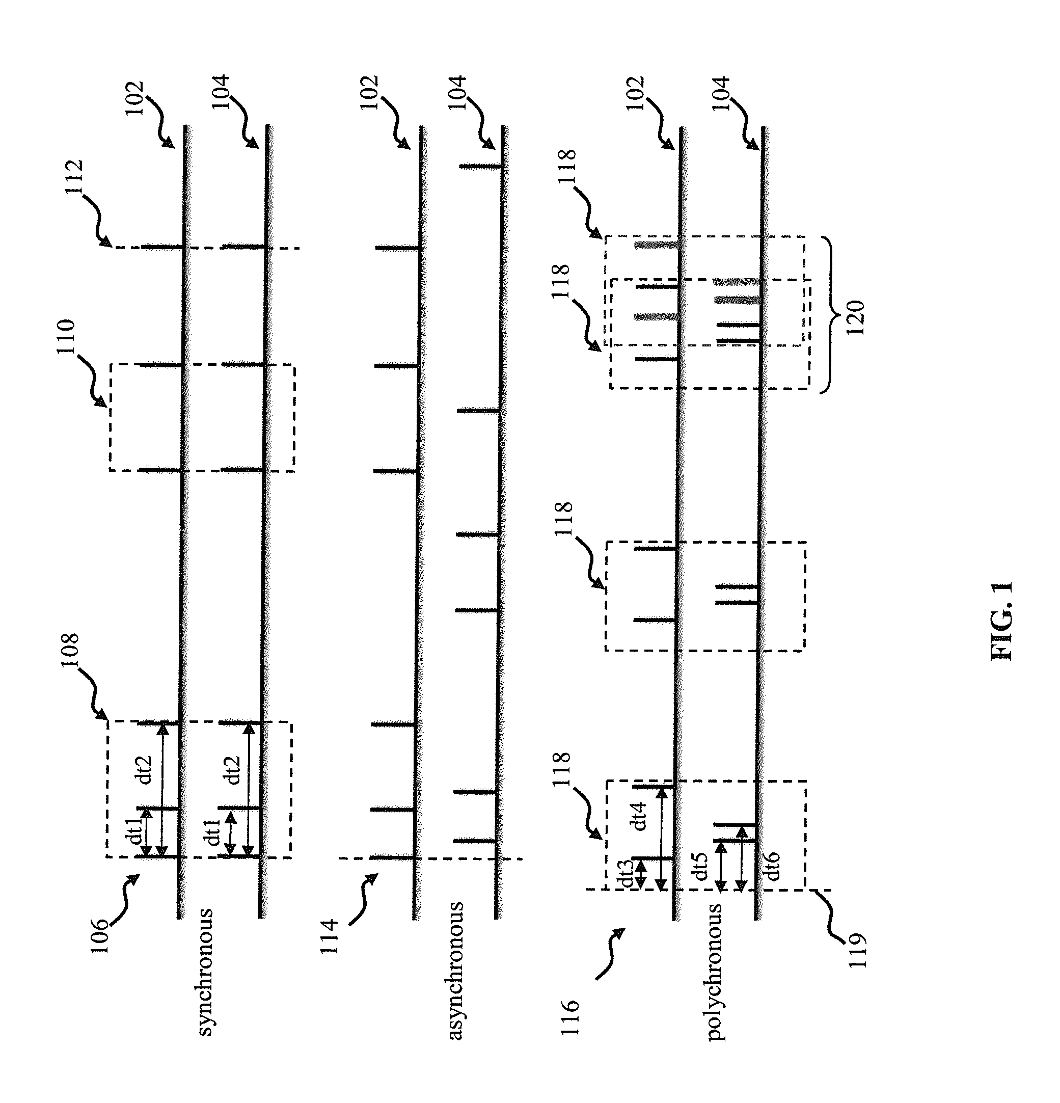
However, when too many photoreceptors are active, the output consists of a synchronous barrage of pulses (e.

Method used


Image

  • Apparatus and methods for polychronous encoding and multiplexing in neuronal prosthetic devices
  • Apparatus and methods for polychronous encoding and multiplexing in neuronal prosthetic devices
  • Apparatus and methods for polychronous encoding and multiplexing in neuronal prosthetic devices

Examples


Embodiment Construction

[0038]Embodiments of the present invention will now be described in detail with reference to the drawings, which are provided as illustrative examples so as to enable those skilled in the art to practice the invention. Notably, the figures and examples below are not meant to limit the scope of the present invention to a single embodiment; other embodiments are possible by way of interchange of, or combination with, some or all of the described or illustrated elements. Wherever convenient, the same reference numbers will be used throughout the drawings to refer to same or like parts.

[0039]Where certain elements of these embodiments can be partially or fully implemented using known components, only those portions of such known components that are necessary for an understanding of the present invention will be described, and detailed descriptions of other portions of such known components will be omitted so as not to obscure the invention.

[0040]In the present specification, an embodime...


PUM


Abstract

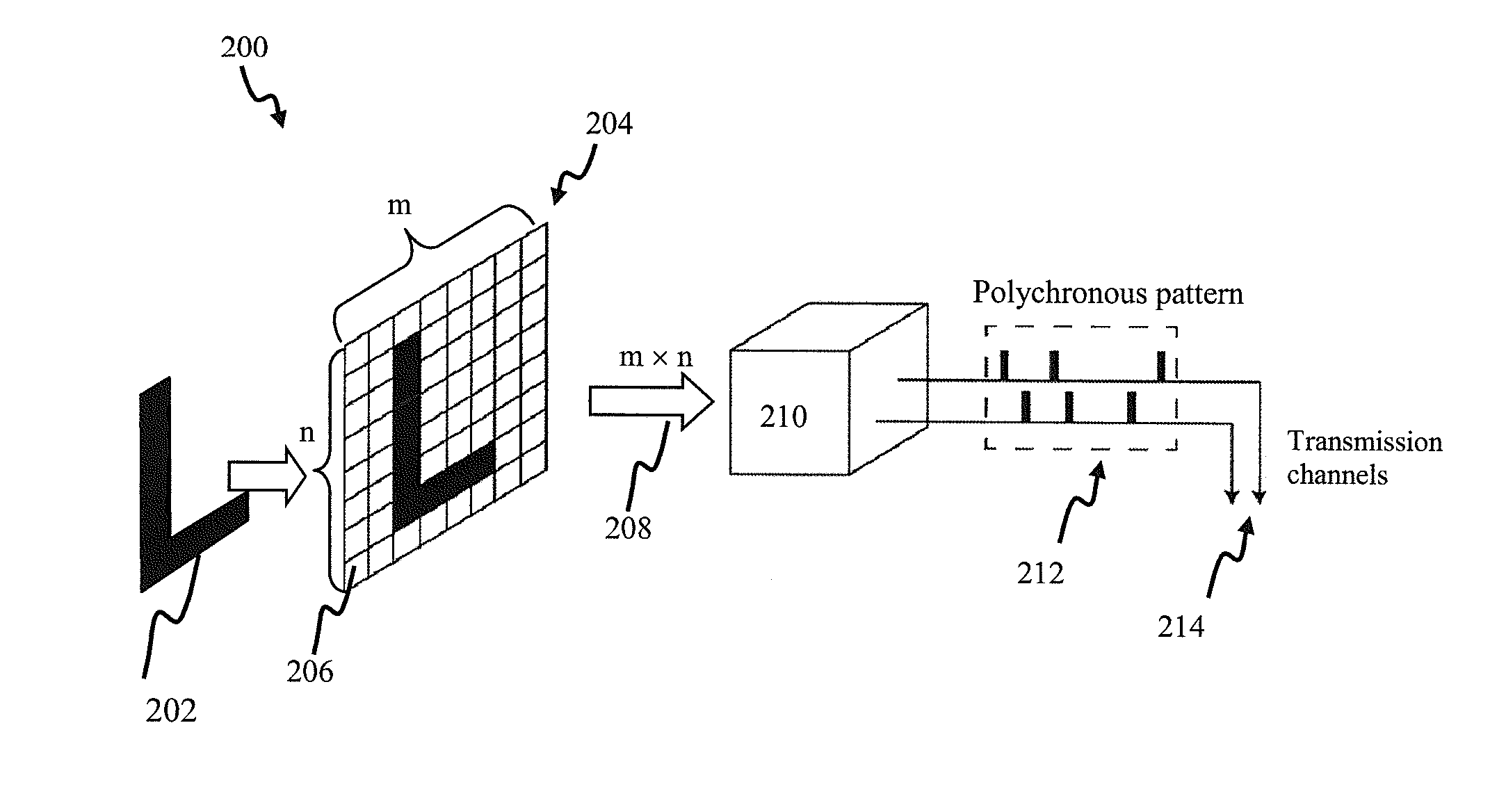
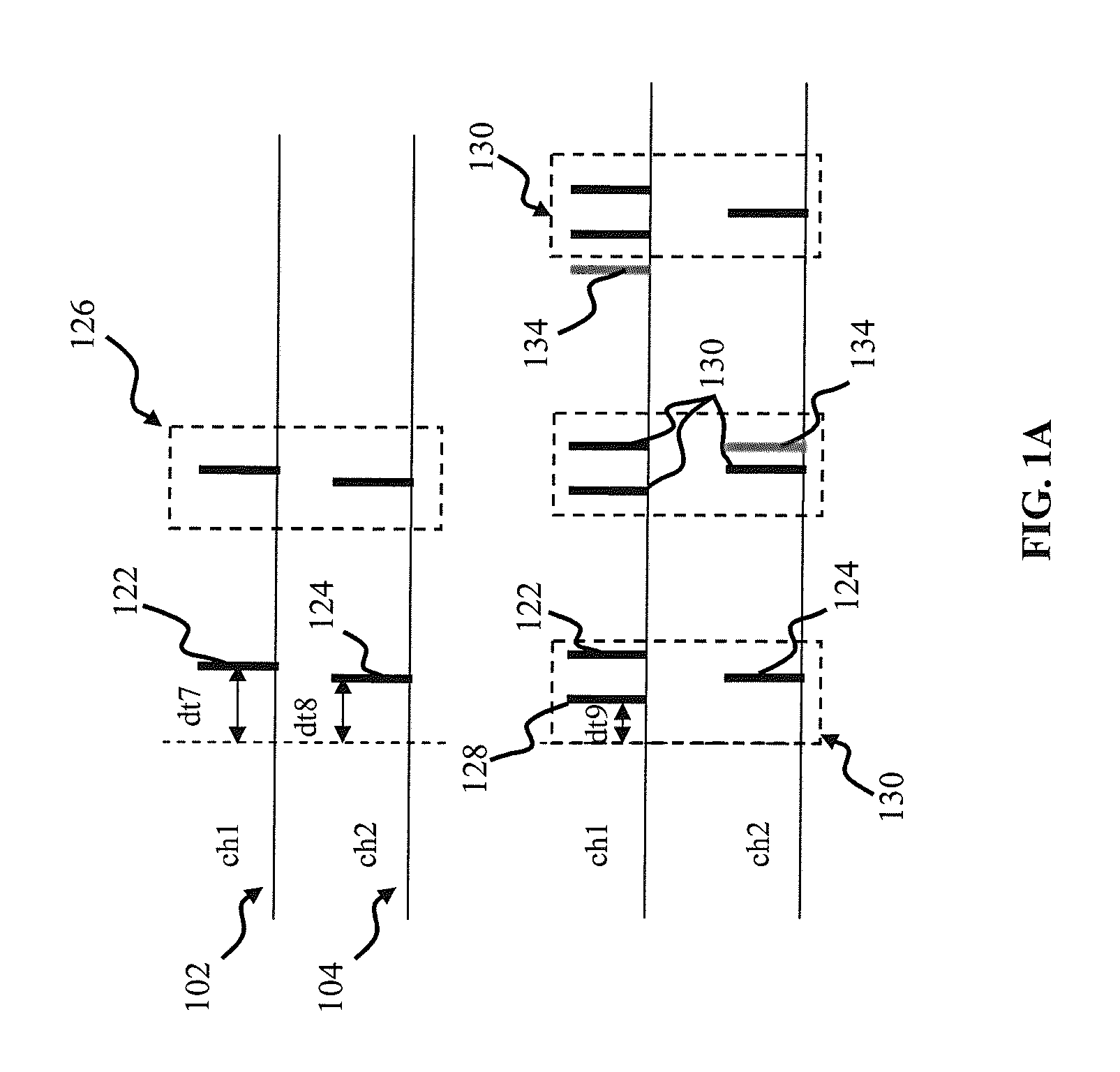
Apparatus and methods for encoding sensory input information into patterns of pulses and message multiplexing. In one implementation, the patterns of pulses are polychronous (time-locked by not necessary synchronous), and a retinal prosthetic encodes the input signal into the polychronous patterns for delivery via stimulating electrodes. Different polychronous patterns simultaneously encode different sensory signals; (such as different features of the image), thus providing for message multiplexing. Increasing data transmission capacity allows for a reduction in the number of electrodes required for data transmission. In one implementation, an adaptive feedback mechanism is employed to facilitate encoder operation. In another aspect, a computer vision system is described.

Description

CROSS-REFERENCE TO RELATED APPLICATIONS[0001]This application is related to co-owned U.S. provisional patent application No. 61 / 318,191, filed Mar. 26, 2010 and entitled “Systems and Method for Pulse-Code Invariant Object Recognition”, U.S. patent application Ser. No. 12 / 869,573, filed Aug. 26, 2010 and entitled “Systems and Methods for Invariant Pulse Latency Coding”, U.S. patent application Ser. No. 12 / 869,583, filed Aug. 26, 2010 and entitled “Invariant Pulse Latency Coding Systems and Methods”, each of the foregoing incorporated herein by reference in its entirety.COPYRIGHT[0002]A portion of the disclosure of this patent document contains material that is subject to copyright protection. The copyright owner has no objection to the facsimile reproduction by anyone of the patent document or the patent disclosure, as it appears in the Patent and Trademark Office patent files or records, but otherwise reserves all copyright rights whatsoever.BACKGROUND OF THE INVENTION[0003]1. Field...

Claims


Application Information

Patent Timeline
IPC IPC(8): A61F9/08A61N1/36
CPCG06N3/049G06F19/36G06F19/3406G16H20/30G16H40/63
Inventor IZHIKEVICH, EUGENE M.
Owner BRAIN CORP
Why Eureka
Try Eureka