System and methods for fault-isolation and fault-mitigation based on network modeling

a network modeling and fault-isolation technology, applied in the field of system and methods for fault-isolation and fault-mitigation based on network modeling, can solve problems such as affecting the operation of the vehicle, eess and ecus are susceptible to errors, failures and faults,

Active Publication Date: 2012-11-29
GM GLOBAL TECH OPERATIONS LLC
View PDF2 Cites 51 Cited by
  • Summary
  • Abstract
  • Description
  • Claims
  • Application Information

AI Technical Summary

Problems solved by technology

Vehicle EESs are becoming much more complex as they have evolved in response to a continuously increasing demand for incorporating electronic and electrical control units (ECUs) into vehicles.
However, the fast growing number of ECUs and their peripherals on a vehicle has led to complex interactions that sometimes cause unexpected behaviors, such as emerging or cascading failures.
As with anything, EESs and ECUs are susceptible to errors, failures and faults that could affect the operation of the vehicle.
All of this information could be corrupted in some fashion, such as a result of loose wiring, memory failure, calculation inaccuracies, etc.
Furthermore, the current techniques employed in integrated vehicle health management (IVHM) and active safety systems are still lacking in standardization and metrics for addressing the needs for improving and quantifying maintainability and complexity in the EESs.
When such errors and faults occur, often the affected device or component will issue a fault code, such as diagnostic trouble code (DTC), that is received by one or more system controllers identifying the fault, or some ancillary fault with an integrated component.
Although it may be desirable on some level to provide monitoring points at every possible location to collect sufficient data to clearly identify a problem, such a scheme is impractical and ultimately too costly.
Known techniques for identifying the best monitoring points in and between an EES and / or ECUs has heretofore been limited.

Method used


Image

  • System and methods for fault-isolation and fault-mitigation based on network modeling
  • System and methods for fault-isolation and fault-mitigation based on network modeling
  • System and methods for fault-isolation and fault-mitigation based on network modeling

Examples


Embodiment Construction

[0014]The following discussion of a system and method for selecting a data monitoring point in a network model of a vehicle EES using a betweenness centrality metric is merely exemplary in nature, and is in no way intended to limit the invention or its applications or uses. For example, as mentioned, the present invention has particular application for an EES on a vehicle. However, as will be appreciated by those skilled in the art, the system and method of the present invention will have application for other systems other than vehicle systems.

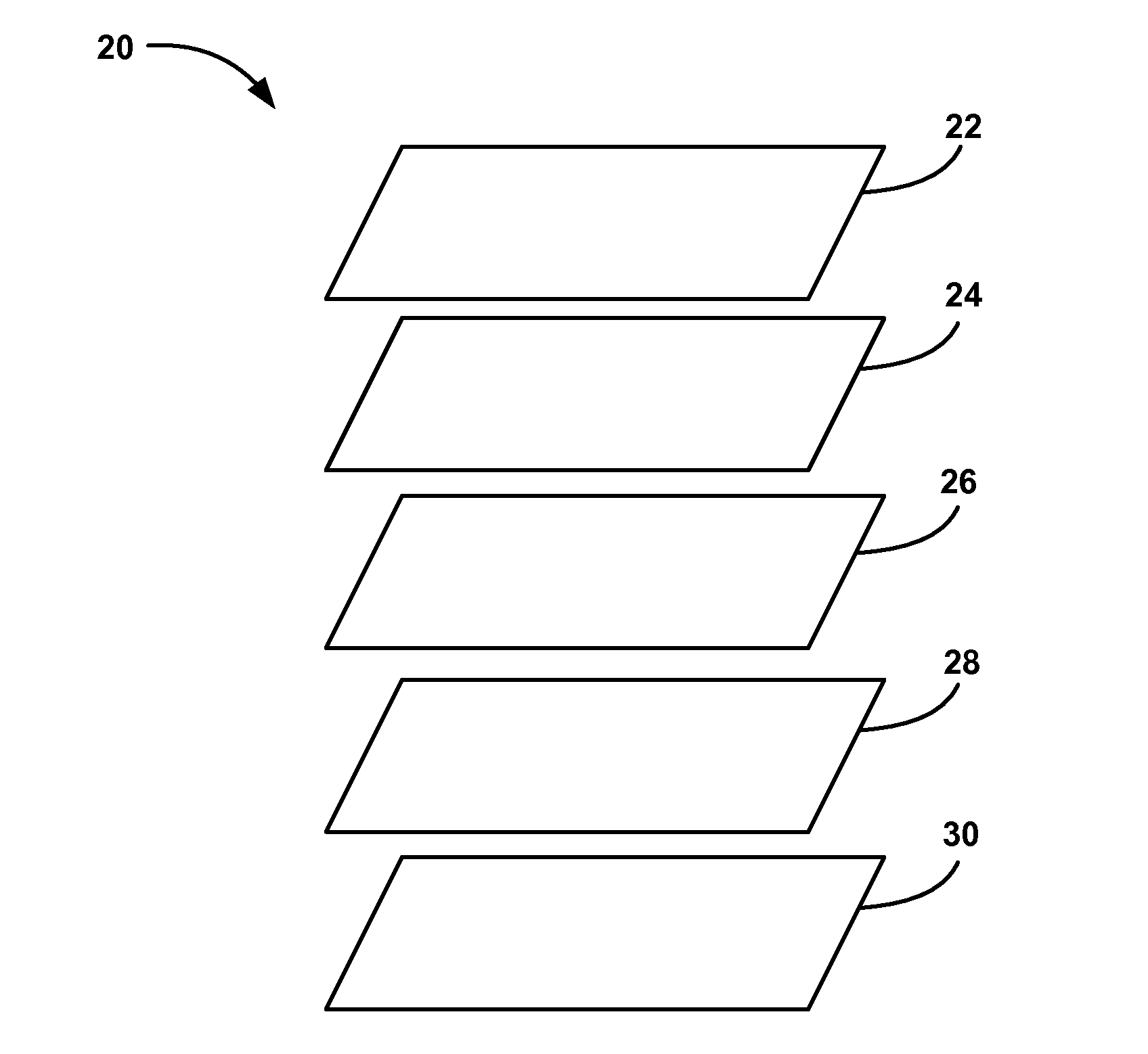
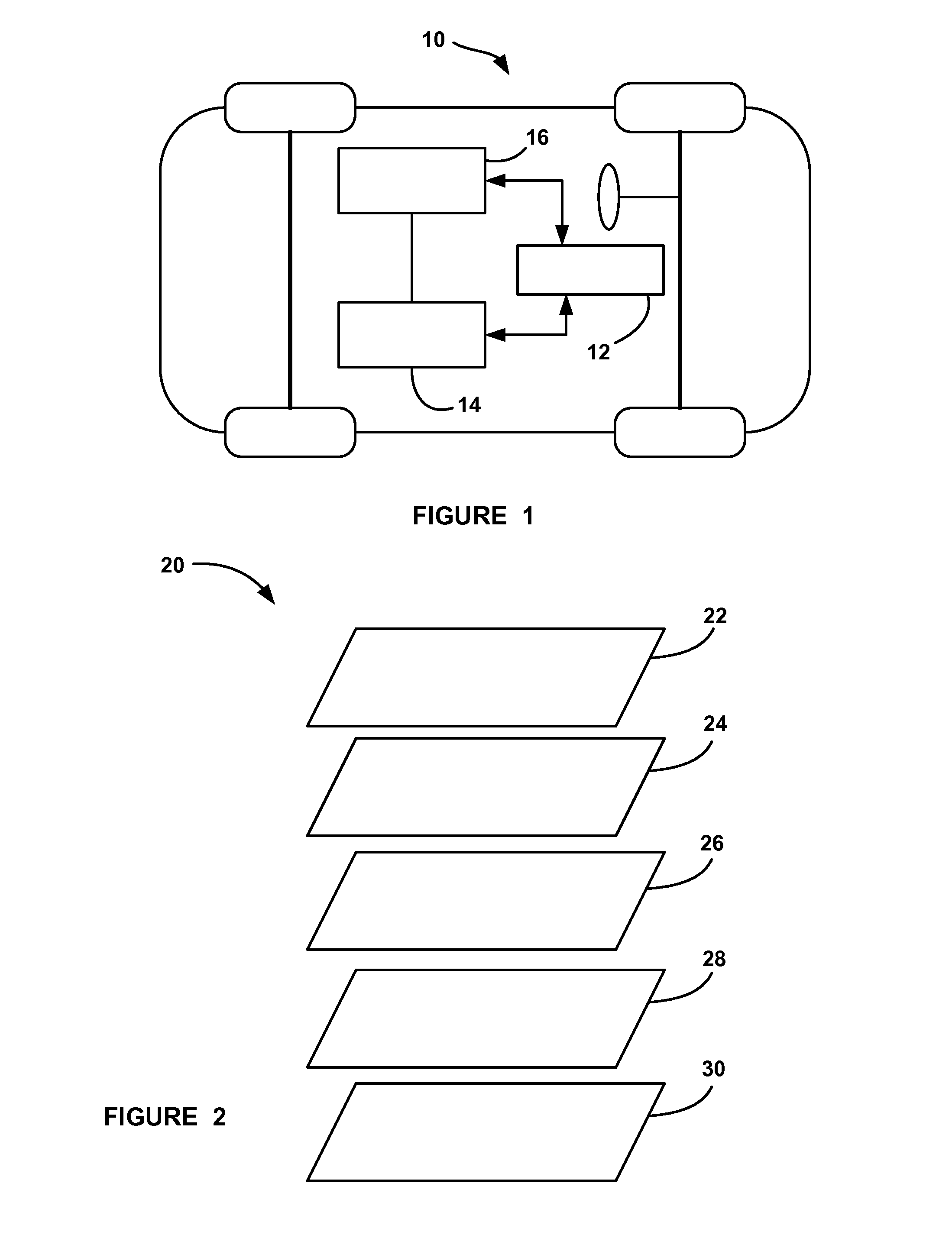
[0015]The present invention proposes a system and method for selecting a data monitoring point in a network model of a vehicle EES for an integrated fault-isolation and mitigation analysis (FIMA) system. The input to the system is the network model that may be a layered network that represents physical, structural, functional and data-flow features of the EES. Each layer in the network provides one aspect of the EES, for example, a physical n...


PUM


Abstract

A system and method for identifying a monitoring point in an electrical and electronic system (EES) in a vehicle. The method includes defining a network model of the EES where potential monitoring point locations in the model are identified as targets, such as nodes. The method then computes a betweenness centrality metric for each target in the model as a summation of a ratio of a total number of shortest paths between each pair of targets and a number of shortest paths that pass through the target whose betweenness centrality metric is being determined. The method identifies which of the betweenness centrality metrics are greater than a threshold that defines a minimum acceptable metric and determines which of those targets meets a predetermined model coverage. The monitoring point is selected as the target that best satisfies the minimum metric and the desired coverage.

Description

BACKGROUND OF THE INVENTION[0001]1. Field of the Invention[0002]This invention relates generally to defining a data monitoring point in a system for integrated fault-isolation and fault-tolerance analysis of an in-vehicle embedded electrical and electronic system (EES) and, more particularly, to a system and method for defining a data monitoring point for integrated fault-isolation and fault-tolerance analysis of an in-vehicle embedded EES that includes defining the EES as a network model, calculating a betweenness centrality metric for each potential monitoring point in the model, ranking the betweenness centrality metrics and selecting the potential monitoring point with the highest betweenness centrality metric as the actual monitoring point if it satisfies a predetermined coverage defined by a degree of neighbor factor.[0003]2. Discussion of the Related Art[0004]Modern vehicles are complex electrical and mechanical systems that employ many components, devices, modules, sub-syste...

Claims


Application Information

Patent Timeline
Patent Type & Authority Applications(United States)
IPC IPC(8): G06G7/62
CPCG05B23/0235B60W50/0205B60W50/045G06F11/3093G06F11/079G06F11/3013G06F11/0739
Inventor LU, TSAI-CHINGZHANG, YILUNIJAMKIN, ALEJANDROALLEN, DAVID L.MOON, HANKYUSALMAN, MUTASIM A.
Owner GM GLOBAL TECH OPERATIONS LLC
Why Eureka
Try Eureka