Stereoscopic image display panel and stereoscopic image display device including the same

a stereoscopic image and display panel technology, applied in the field of stereoscopic image display panels and stereoscopic image display devices, can solve the problems of image quality degradation, explosion of demand for various types of flat panel display devices, etc., and achieve the effect of enhancing brightness and aperture ratio, and minimizing image quality degradation

Inactive Publication Date: 2012-12-06
LG DISPLAY CO LTD
View PDF4 Cites 12 Cited by
  • Summary
  • Abstract
  • Description
  • Claims
  • Application Information

AI Technical Summary

Benefits of technology

[0009]Accordingly, the present invention is directed to provide a stereoscopic image display panel and a stereoscopic image display device including the same, which minimize the degradation of image quality due to crosstalk between left and right images discerned by a viewer, and have enhanced brightness and aperture ratio.

Problems solved by technology

Due to such requirements, there is the explosive increase in demand on various types of flat panel display devices that are thin, light, and have a low consumption power.
Stereoscopic image display devices of the related art have limitations in that image quality is degraded due to crosstalk between a left image and a right image.

Method used


Image

  • Stereoscopic image display panel and stereoscopic image display device including the same
  • Stereoscopic image display panel and stereoscopic image display device including the same
  • Stereoscopic image display panel and stereoscopic image display device including the same

Examples


Embodiment Construction

[0021]Reference will now be made in detail to the exemplary embodiments of the present invention, examples of which are illustrated in the accompanying drawings. Wherever possible, the same reference numbers will be used throughout the drawings to refer to the same or like parts.

[0022]Hereinafter, embodiments of the present invention will be described in detail with reference to the accompanying drawings.

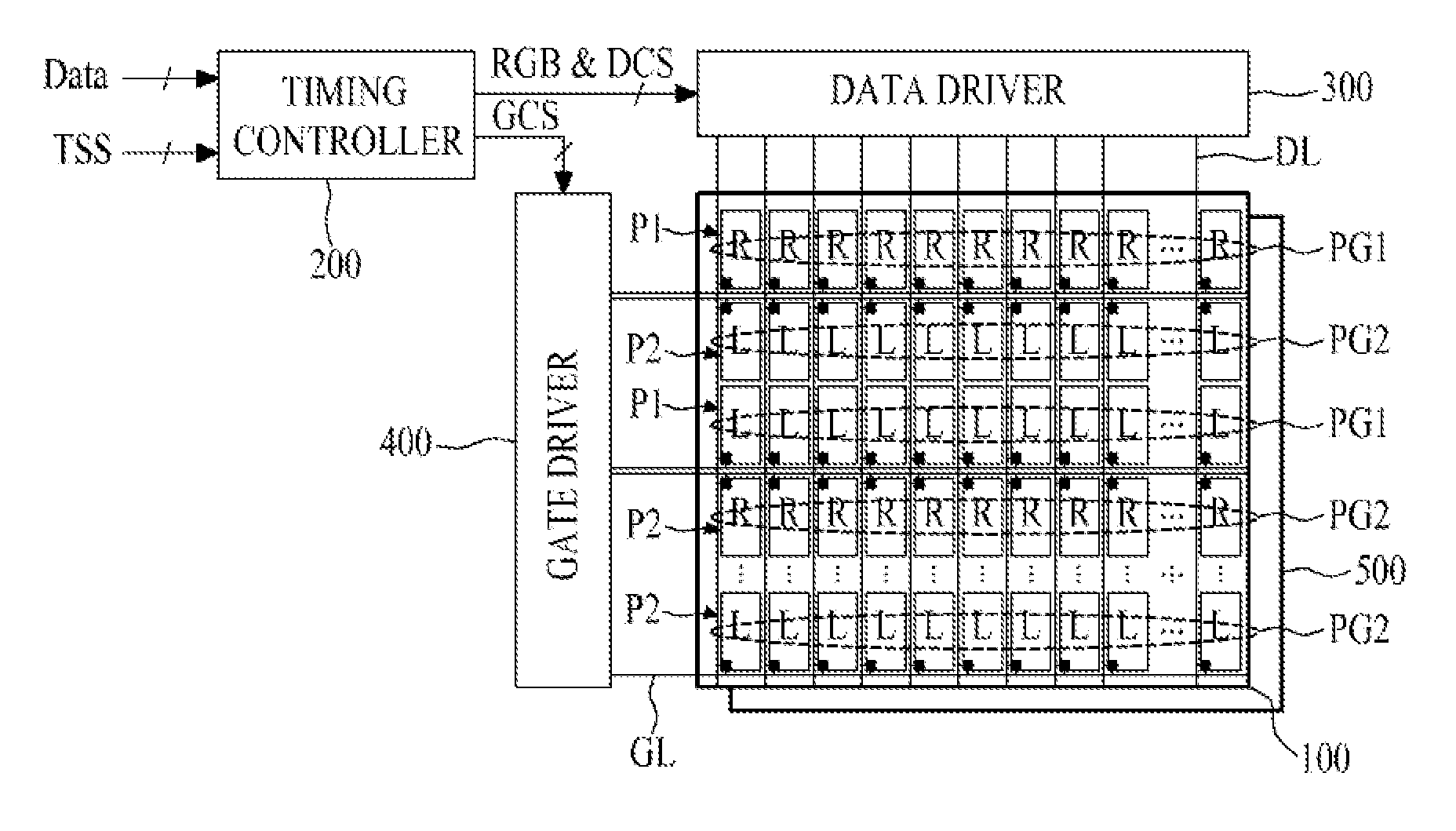
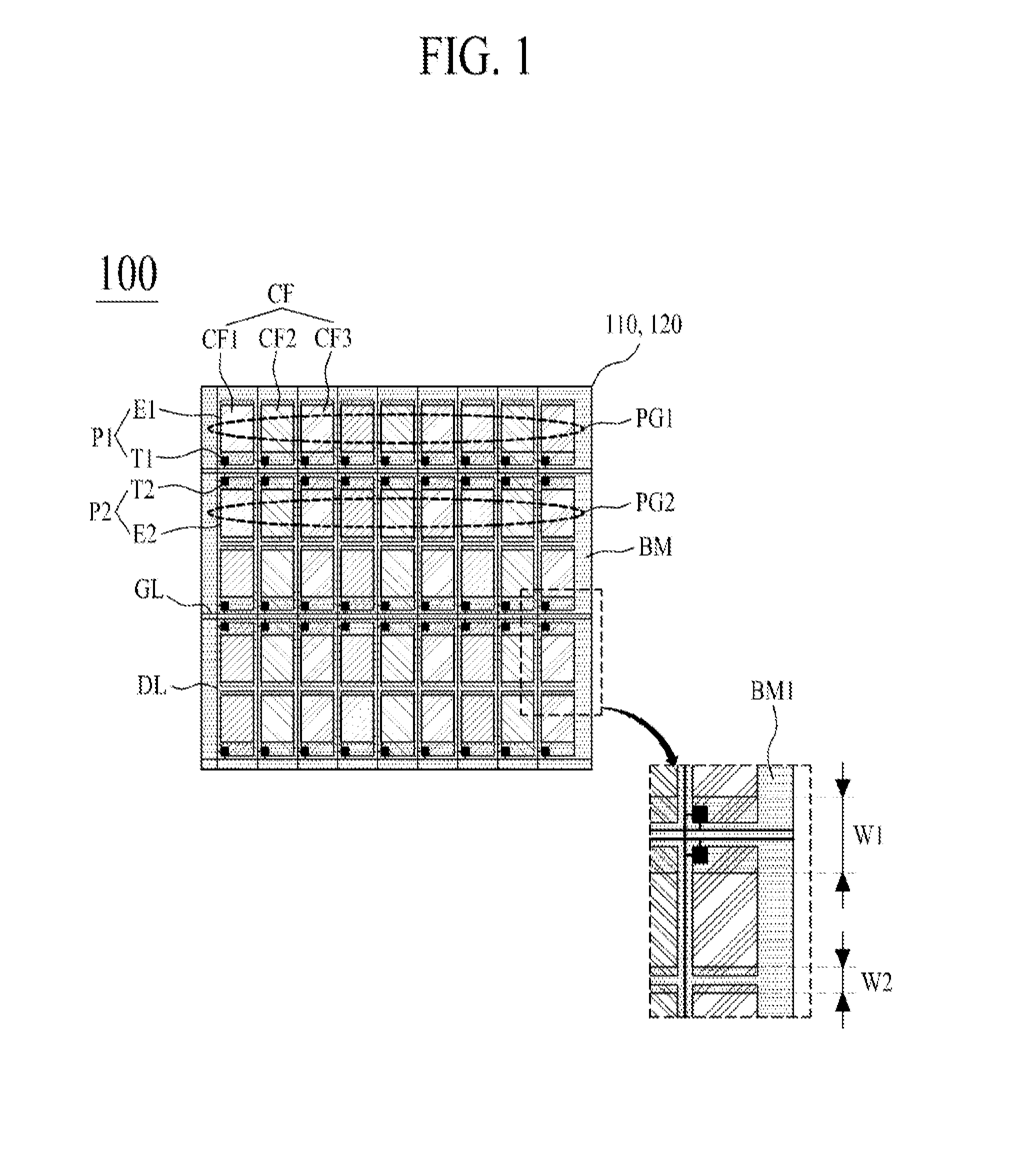
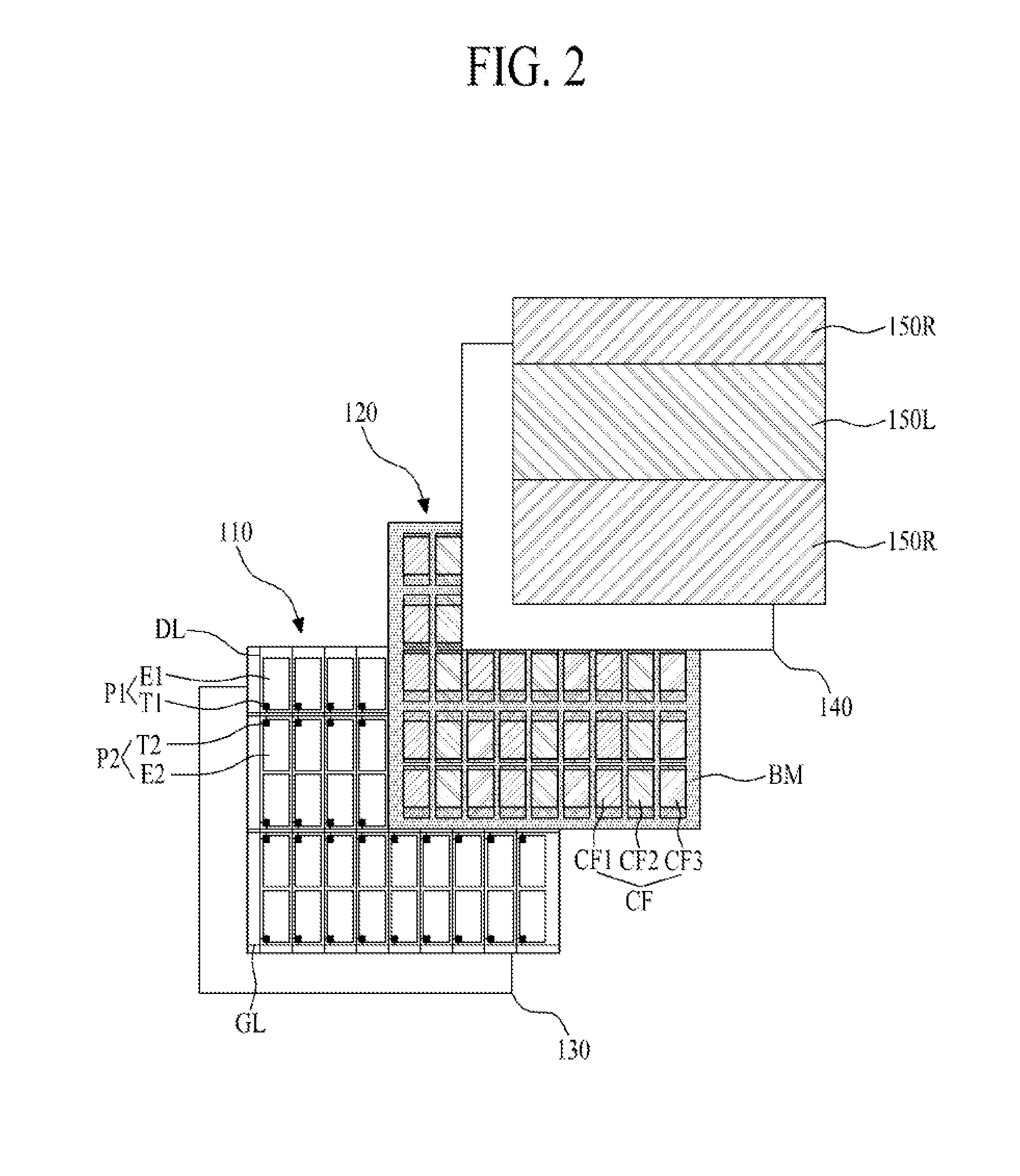
[0023]FIG. 1 is a plan view illustrating a stereoscopic image display panel according to an embodiment of the present invention. FIG. 2 is an exploded perspective view illustrating a portion of the stereoscopic image display panel of FIG. 1.

[0024]Referring to FIGS. 1 and 2, a plan view illustrating a stereoscopic image display panel 100 according to an embodiment of the present invention includes first and second substrates 110 and 120, first and second polarizers 130 and 140, first and second optical axis changing members 150R and 150L.

[0025]The first and second substrates 110 are ...


PUM

PropertyMeasurementUnit
widthaaaaaaaaaa
three-dimensionaaaaaaaaaa
transmittanceaaaaaaaaaa

Abstract

Disclosed is a stereoscopic image display panel and a stereoscopic image display device including the same, which minimize the degradation of image quality due to crosstalk between left and right images discerned by a viewer, and have enhanced brightness and aperture ratio, wherein the stereoscopic image display panel comprises a first substrate including a plurality of data lines formed at certain intervals apart, a plurality of gate lines formed to intersect the data lines, and first and second pixel groups formed adjacently to each other with two adjacent gate lines therebetween; and a second substrate including a light shield layer formed at one side and other side of each of the first and second pixel groups to have different overlapped widths, and defining an open area of each of the first and second pixel groups, wherein the first and second pixel groups display different stereoscopic images, respectively.

Description

BACKGROUND OF THE INVENTION[0001]1. Field of the Invention[0002]The present invention relates to a stereoscopic image display device, and more particularly, to a stereoscopic image display panel and a stereoscopic image display device including the same, which minimize the degradation of image quality due to crosstalk between left and right images discerned by a viewer, and have enhanced brightness and aperture ratio.[0003]2. Discussion of the Related Art[0004]With the advance of information society, enlarging and thinning of display devices are being required in the market. Due to such requirements, there is the explosive increase in demand on various types of flat panel display devices that are thin, light, and have a low consumption power.[0005]As flat panel display devices, there are liquid crystal display devices (LCDs), plasma display panels (PDPs), field emission display devices (FEDs), and light-emitting diode display devices (LEDs) that are actively being researched. Among ...

Claims


Application Information

Patent Timeline
Patent Type & Authority Applications(United States)
IPC IPC(8): G09G3/36G09G5/10G02F1/1335G06F3/038
CPCG09G3/003G09G3/3648H04N13/0434G02B27/26G09G2300/0426H04N13/337G02B30/25
Inventor JEONG, IL GILEE, SU WOONGGONG, NAM YONGPARK, CHONG HUN
Owner LG DISPLAY CO LTD
Why Eureka
Try Eureka