Display Device

a display device and display angle technology, applied in optics, instruments, electrical devices, etc., can solve the problems of low out-coupling efficiency of emitting displays, reduced light efficiency, and greatly limited viewing angle of lcds, so as to prevent image quality from being degraded, minimize color shift, and improve image quality

Inactive Publication Date: 2012-12-06
SAMSUNG CORNING PRECISION MATERIALS CO LTD
View PDF4 Cites 30 Cited by
  • Summary
  • Abstract
  • Description
  • Claims
  • Application Information

AI Technical Summary

Benefits of technology

[0057]According to embodiments of the invention, it is possible to improve image quality by minimizing color shift due to an increase in the viewing angle and to prevent the image quality from being degraded by the moiré phenomenon by calculating an optimum parameter for a pattern pitch and applying the optimum parameter.
[0058]In addition, according to embodiments of the invention, it is possible to reduce ghosting and hazing by directly attaching the optical film to the display panel or bringing the optical film into contact with the display panel via adhesion.

Problems solved by technology

Accordingly, the viewing angle of the LCD is greatly limited compared to other displays, which intrinsically emit light, since the intensity and color of light of the LCD varies depending on changes in the viewing angle.
However, the organic light-emitting display has the problem of low out-coupling efficiency.
One of factors that decrease the light efficiency is the presence of light that exits in an unnecessary direction when emitted from the substrate having a higher refractive index to the air having a lower refractive index.
However, in addition to the above advantage, the organic light-emitting display having the micro-cavity structure has the drawback of the decreased viewing angle due to color shift.
This consequently causes a problem in that the light that resonates and exits is further shifted to a short wavelength as the optical path is increased at the side.

Method used


Image

  • Display Device
  • Display Device
  • Display Device

Examples


Embodiment Construction

[0076]Reference will now be made in detail to an optical film and a display device having the optical film according to the invention, embodiments of which are illustrated in the accompanying drawings and described below.

[0077]In the following description of the present invention, detailed descriptions of known functions and components incorporated herein will be omitted when they may make the subject matter of the present invention unclear.

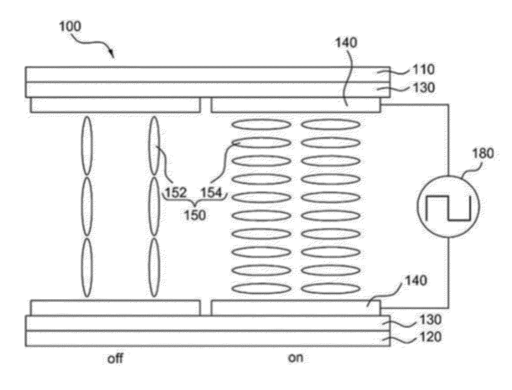
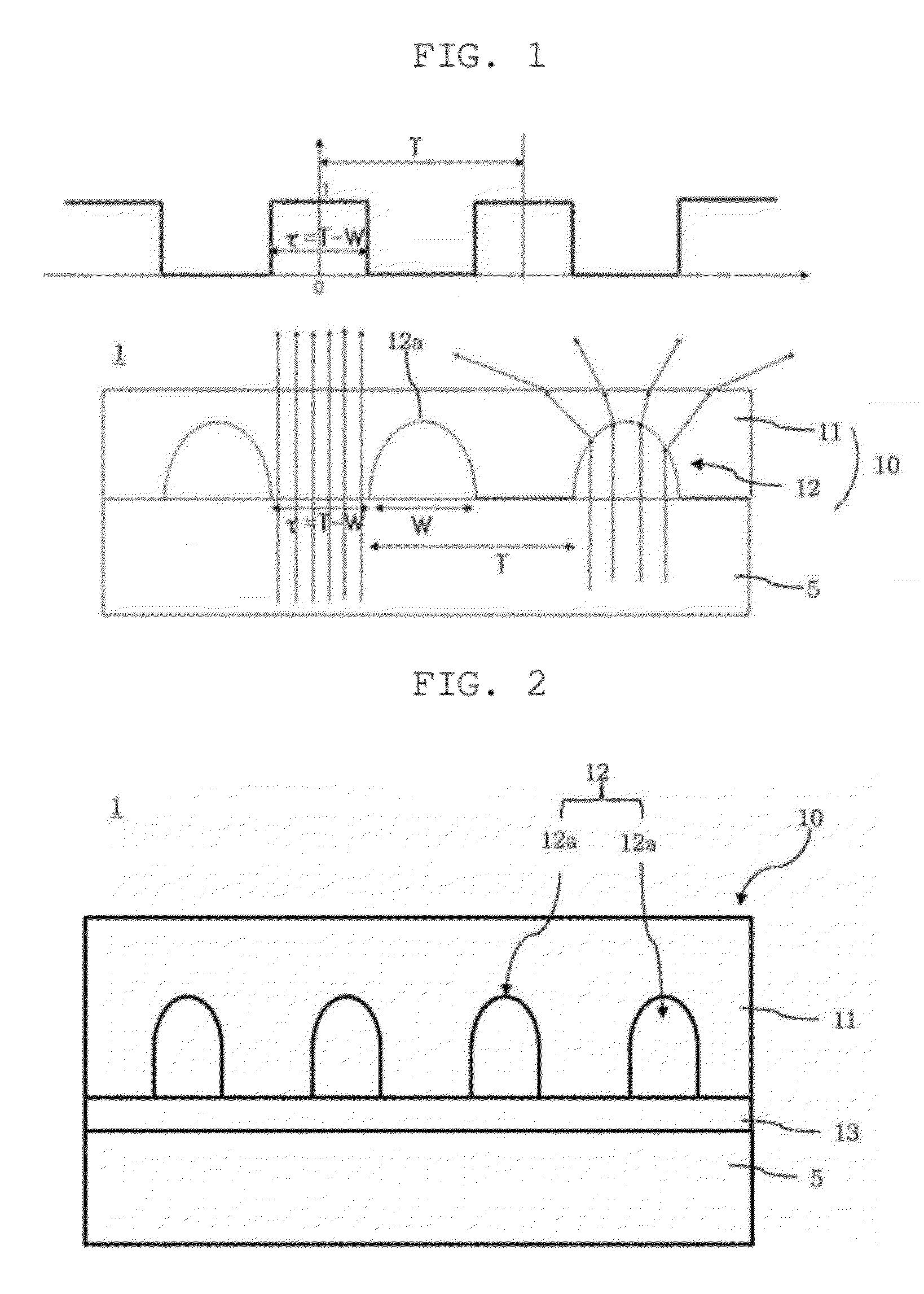
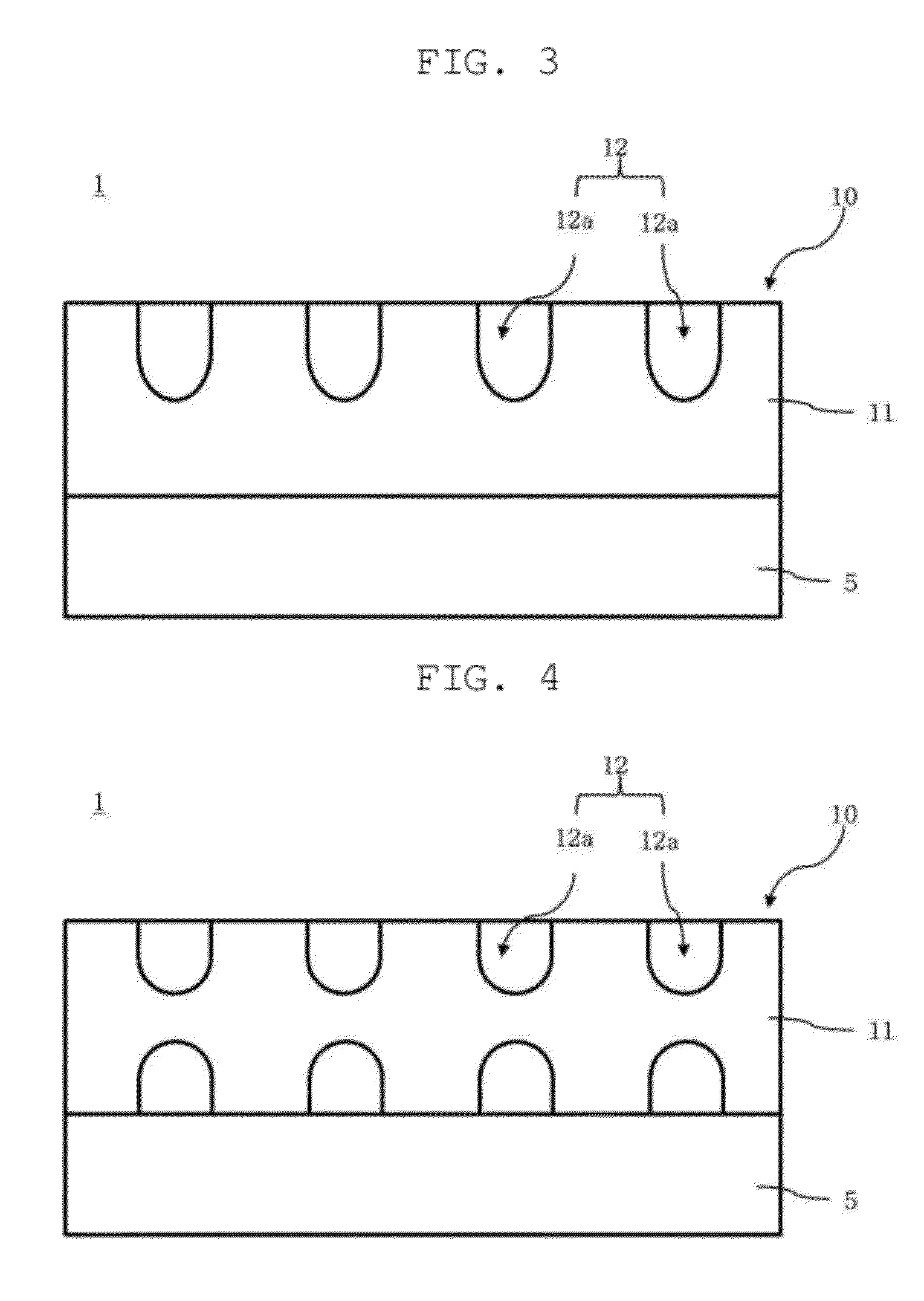
[0078]Referring to FIG. 1, an optical film 10 according to an exemplary embodiment of the invention is a film that is devised to prevent a moiré phenomenon while reducing color shift in a display device 1. In an example, the display device 1, which employs the optical film 10, may be a liquid crystal display. Here, the optical film 10 may be disposed on the front surface of a liquid crystal display panel 5, which has a liquid crystal layer interposed between two opposing substrates. In another example, the display device 1, which employs the opti...


PUM

PropertyMeasurementUnit
refractive indexaaaaaaaaaa
thicknessaaaaaaaaaa
refractive indexaaaaaaaaaa

Abstract

A display device that can reduce color shift and prevent the quality of an image from degrading due to moiré. The display device includes a display panel and an optical film, which includes a background layer disposed in front of the display panel, and a lens section formed on the background layer. Patterns of the lens section is spaced apart from each other to diffuse incident light. The spacing τ and pitch T of the patterns are determined by the following m value in the following formulae.
Imax-IminImax+Imin2sin(π·k·p/P)(π·k·p/P)sin(π·m·p/P)(π·m·p/P)0.01k=τ/Tp/Pm=P/T
p/P is an aperture ratio of sub-pixels of the display panel, τ/T is an aperture ratio of the lens section, I is an intensity of light exiting the optical film after being diffused through the sub-pixels, P and p are a pitch and a width of the sub-pixels, T is a pitch of the patterns, and τ=T−W.

Description

CROSS REFERENCE TO RELATED APPLICATION[0001]The present application claims priority from Korean Patent Application Numbers 10-2011-0051584 filed on May 30, 2011 and 10-2011-0060522 filed on Jun. 22, 2011, the entire contents of which applications are incorporated herein for all purposes by this reference.BACKGROUND OF THE INVENTION[0002]1. Field of the Invention[0003]The present invention relates to a display device, and more particularly, to a display device that can not only reduce color shift but also prevent the quality of an image from degrading due to a moiré phenomenon.[0004]2. Description of Related Art[0005]In response to the emergence of the advanced information society, components and devices related to image displays have been significantly improved and rapidly disseminated. Among them, image display devices have been widely distributed for use in. TVs, personal computer (PC) monitors, and the like. Moreover, attempts are underway to simultaneously increase the size and ...

Claims


Application Information

Patent Timeline
Patent Type & Authority Applications(United States)
IPC IPC(8): G02F1/1343
CPCG02B3/0037G02F1/133504G02F1/133526G02B5/0294H01L51/5275G02B5/0236G02F2001/133562G02F1/133562H10K50/858
Inventor PARK, SEONG-SIKKIM, EUISOOKIM, JOOSOKSHIN, YOU MINLEE, JINHOONCHO, EUNYOUNG
Owner SAMSUNG CORNING PRECISION MATERIALS CO LTD
Why Eureka
Try Eureka