LED plastic heat sink and method for making and using the same

a heat sink and led technology, applied in the field of heat sinks, can solve the problems of increased cost and processing difficulties, performance degradation or even damage, and the size of metal core printed circuit boards, and achieve the effects of enhancing productivity, reducing weight, and enhancing design freedom

Active Publication Date: 2012-12-06
SHPP GLOBAL TECH BV
View PDF3 Cites 76 Cited by
  • Summary
  • Abstract
  • Description
  • Claims
  • Application Information

AI Technical Summary

Problems solved by technology

The high power LED light devices produce considerable amount of heat, which may cause performance degradation or even damage if the heat is not removed from the LED chips efficiently.
While metal core printed circuit boards are effective for dissipating heat, disadvantages are increased costs and processing difficulties.
In addition, since there are limitations to the size of metal core printed circuit boards, they are more difficult to incorporate into larger size devices.
A disadvantage of this approach is that it is a labor-intensive process, resulting in increased costs.
In addition, the resulting configuration is subject to high failure rates.
However, due to productivity issues and secondary operations such as painting of the die cast material, alternative designs to heat sink systems employing aluminum heat sinks also are being sought.

Method used


Image

  • LED plastic heat sink and method for making and using the same
  • LED plastic heat sink and method for making and using the same
  • LED plastic heat sink and method for making and using the same

Examples


example 1

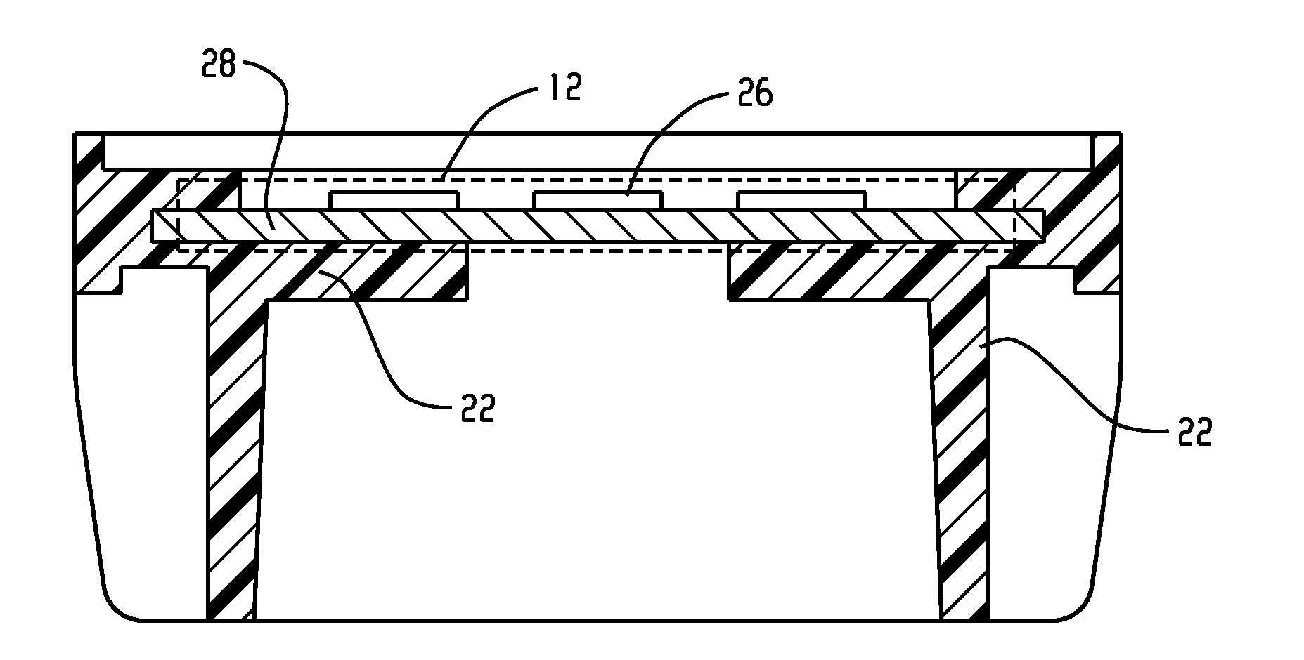
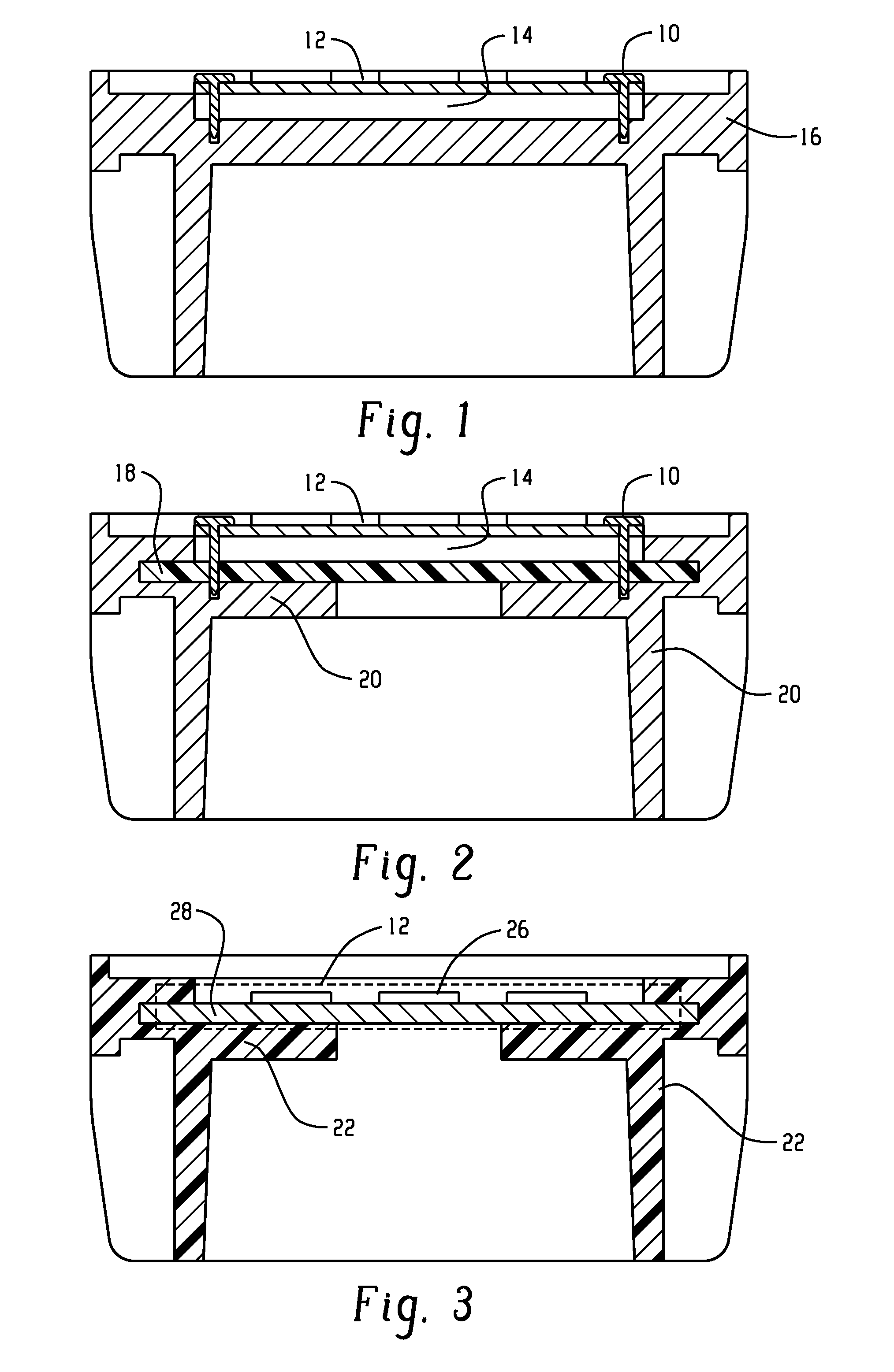
[0081]Thermal CAE (computer aided engineering) analysis (simulation) comparing a baseline design with hybrid design architecture described herein (e.g., FIG. 2 including a plastic heat sink). FIG. 1 illustrates an aluminum baseline design. FIGS. 2 and 3 are the models used for analysis. For all 3 samples, the outer diameter with the fins is 58 mm, the height of the heat sink is 33 mm, the number of fins is 24, the wall thickness is 1.5 mm, and the volume is approximately 20.6 cm3.

[0082]As the material changed from aluminum (Al) to plastic in the hybrid design, the degree of design freedom enables designers to achieve comparable heat dissipation performance of an Al heat sink. Accordingly, comparison only between the plastic architecture set forth herein and the hybrid design is reasonable. In this computer simulation, it is assumed that there is no air gap during TIM processing in the hybrid design.

[0083]The LED junction temperature of the design for FIG. 1 is 51.09° C. while the hy...

example 2

[0084]Thermal CAE (computer aided engineering) analysis (simulation) was conducted on various hybrid designs proposed herein. For a three watt heat source on a LED chip, simulations were conducted to determine the effectiveness of these designs. For all of the tested designs, a reduction in temperature of the LED chip was observed. More specifically, Table 1 below sets forth the results of the thermal analysis testing on these hybrid designs. Sample 1, considered as the baseline case, is illustrated in FIG. 19A; Sample 2 including lancing provisions 86 is illustrated in FIG. 19B; Sample 3 including embossing 90 (height of 1.4 mm) is illustrated in FIG. 19C; and Sample 4 including lancing provisions 86 with inside fins 44 is illustrated in FIG. 19D, with a height of 4 mm and radius of 3 mm (see FIG. 20). All of Samples 1-4 had the same the outer diameter with the fins of 58 mm, the height of the heat sink of 33 mm, the number of fins of 24, the wall thickness of 1.5 mm, and the volum...


PUM

PropertyMeasurementUnit
temperatureaaaaaaaaaa
particle sizesaaaaaaaaaa
sizesaaaaaaaaaa

Abstract

In an embodiment, heat sink system can comprise: an integrally formed plastic heat sink and a printed circuit board package, wherein the plastic heat sink comprises a thermally conductive plastic having a thermal conductivity of at least 1.0 W / mK. In another embodiment, hybrid heat sink system, comprising: an integrally formed plastic heat sink and an insert, wherein the plastic heat sink comprises a thermally conductive plastic, the plastic heat sink and the insert each having a cylindrical shape, and wherein the insert comprises a feature of lancing provisions, corrugations, embossing, holes, or a combination comprising at least one of the foregoing features.

Description

CROSS REFERENCE TO RELATED APPLICATIONS[0001]This application claims priority to U.S. Provisional Application No. 61 / 491,546, filed May 31, 2011, the contents of which are hereby incorporated by reference.BACKGROUND[0002]Disclosed herein are heat sinks, and especially light emitting diode (LED) heat sinks and methods of making and using the same.[0003]Light emitting diodes (LEDs) are currently used as replacements for incandescent light bulbs and fluorescent lamps. LEDs are semiconductor devices that emit incoherent narrow-spectrum light when electrically biased in the forward direction of their PN junctions, and are thus referred to as solid-state lighting devices. The high power LED light devices produce considerable amount of heat, which may cause performance degradation or even damage if the heat is not removed from the LED chips efficiently. In an LED light device, the core is a LED chip mounted on a substrate. A transparent top covering the LED chip serves as a lens for modify...

Claims


Application Information

Patent Timeline
Patent Type & Authority Applications(United States)
IPC IPC(8): F28F21/06H05K7/20F21V29/00
CPCF21K9/90F21Y2101/02F21S48/1109F21S48/115F21S48/212F21V29/87F21S48/328F21V29/70F21V29/713F21V29/773F21V29/83F21S48/215F21Y2115/10F21S41/192F21S41/143F21S43/195F21S43/14F21S45/48F21S41/151B29C45/14639B29C45/0001B29K2995/0013F21V29/89
Inventor TANKALA, TRILOKA CHANDERNARAYANASWAMY, VENKATESHAPARAMESHWARA, ARUNACHALAKUSHALAPPA, POOVANNA THEETHIRAKANG, SEONGNAM
Owner SHPP GLOBAL TECH BV
Why Eureka
Try Eureka