Radio base station and relay device

Inactive Publication Date: 2012-12-06
NTT DOCOMO INC
View PDF17 Cites 28 Cited by
  • Summary
  • Abstract
  • Description
  • Claims
  • Application Information

AI Technical Summary

Benefits of technology

[0009]Hence, the present invention has been made in light of the problem described above, and an object of the present invention is to provide a radio base station and a

Problems solved by technology

In the device configuration as shown in FIG. 6, there has conventionally been a problem that since a difference in the frame timing canno

Method used


Image

  • Radio base station and relay device
  • Radio base station and relay device
  • Radio base station and relay device

Examples


Embodiment Construction

(Radio Base Station According to the First Embodiment of the Invention)

[0020]A radio base station according to the first embodiment of the invention will be described with reference to FIG. 1 through FIG. 4.

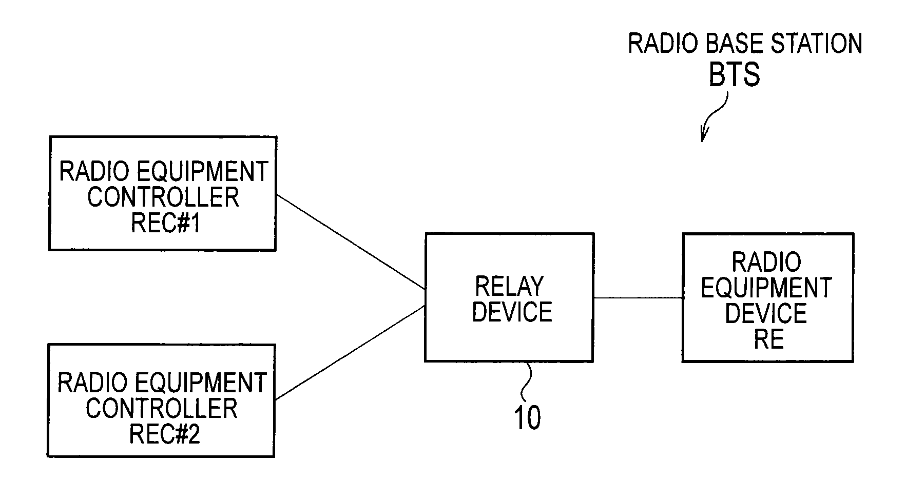
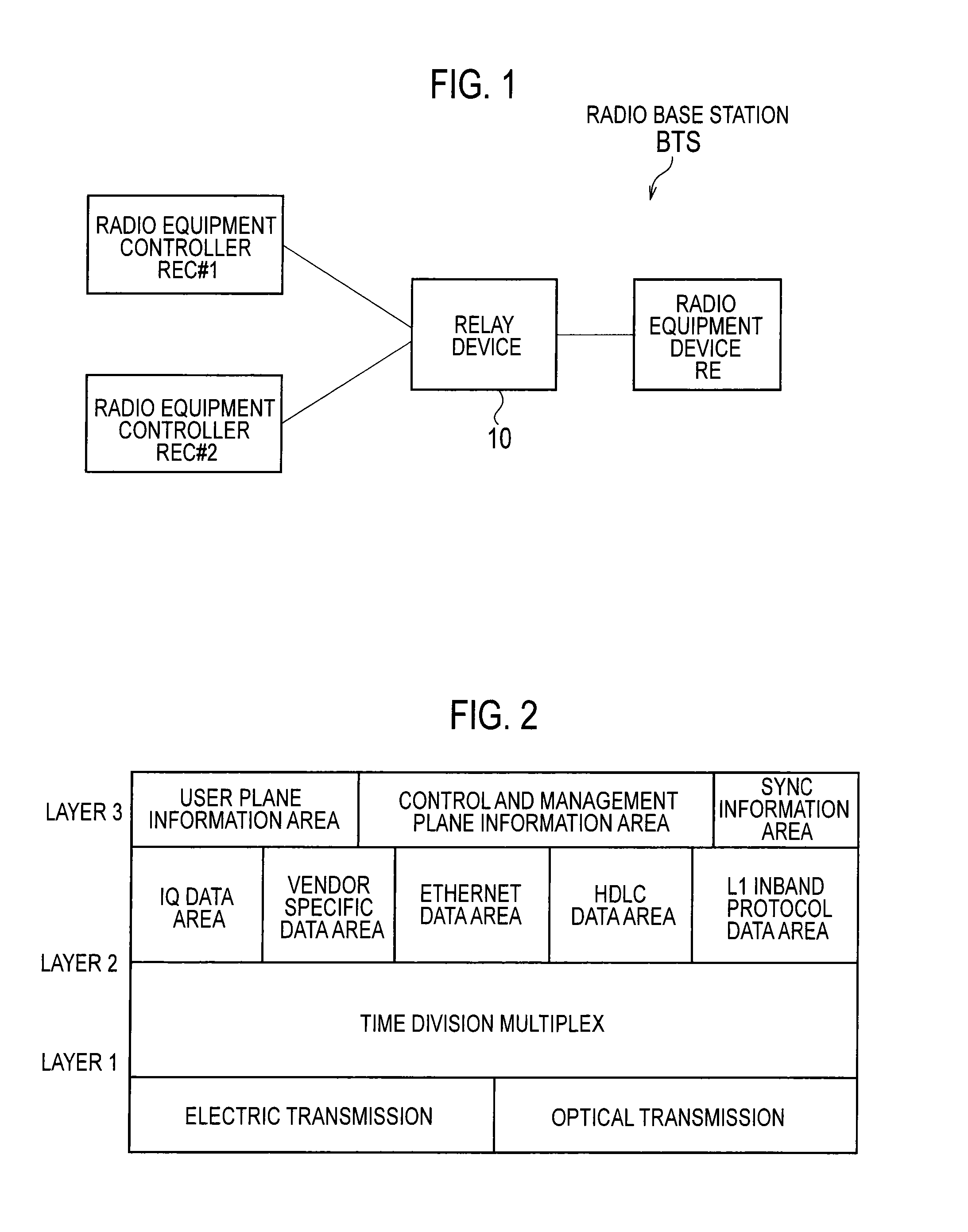
[0021]As shown in FIG. 1, a radio base station BTS according to the embodiment is provided with a radio equipment device RE, a relay device 10, and multiple radio equipment controllers REC#1, REC#2.

[0022]Here, the radio equipment device RE, the relay device 10, and the radio equipment controllers REC#1, REC#2 are separate devices, and connected to each other via a physical line such as an optical line, an electric line, or the like. For example, the radio equipment device RE, the relay device 10, and the radio equipment controllers REC#1, REC#2 are those specified by CPRI.

[0023]For example, the radio equipment controller REC#1 is a radio equipment controller REC for W-CDMA system, and the radio equipment controller REC#2 is a radio equipment controller REC for LTE system. Hereina...


PUM


Abstract

A radio base station BTS according to the present invention includes a timing adjustment unit 15 configured to adjust transmission timing of the frame to be transmitted by a second synchronous signal transmission unit, 12 based on processing delay time in the relay device 10 and round-trip time RTT of the radio equipment device RE at the relay device 10, and the radio equipment controller REC#1, #2 are configured to calculate round-trip time RTT of the radio equipment device RE at the radio equipment controller REC#1, #2, based on a difference T14 between transmission time of the first synchronous signal R1 and reception time of the fourth synchronous signal R4.

Description

TECHNICAL FIELD[0001]The present invention relates to a radio base station and a relay device.BACKGROUND ART[0002]Conventionally, CPRI (Common Public Radio Interface) has specified a radio base station BTS (Base Transceiver Station) which includes a radio equipment device RE and a radio equipment controller REC (Radio Equipment Control) and is configured to transmit and receive a signal between the radio equipment device RE and the radio equipment controller REC via a physical line such as an optical line, an electrical line, or the like.[0003]As shown in FIG. 5, the radio equipment controller REC and the radio equipment device RE insert a synchronous signal “SYNC” at a head position of each hyper frame and transmit the hyper frame. The radio equipment controller REC is configured to insert a first synchronous signal into “SYNC” in each hyper frame and transmit the first synchronous signal to the radio equipment device RE, and to acquire a second synchronous signal inserted into “SY...

Claims


Application Information

Patent Timeline
IPC IPC(8): H04B7/14
CPCH04B7/2606H04W88/085H04W56/009
Inventor WATANABE, TAKAYUKI
Owner NTT DOCOMO INC
Why Eureka
Try Eureka