Signaling and channel estimation for uplink transmit diversity

a channel estimation and transmission technology, applied in the field of wireless communications, can solve the problems of large degradation of performance, high peak-to-average power ratio (papr) inherent in the transmitted signal, increase of both bit error rate (ber) and out-of-band radiation

Active Publication Date: 2012-12-06
NORTEL NETWORKS LTD
View PDF3 Cites 26 Cited by
  • Summary
  • Abstract
  • Description
  • Claims
  • Application Information

AI Technical Summary

Problems solved by technology

A major problem with the multi-carrier modulation in general and OFDM communication systems in particular is the high peak-to-average power ratio (PAPR) that is inherent in the transmitted signal.
Such large signal peaks may saturate the power amplifier (PA) at the transmitter and thus, cause nonlinear distortion of the transmitted signal, which results in a large degradation of performance, e.g. increase of both the bit error rate (BER) and the out-of-band radiation (spectral spreading).
However, when it comes to UL transmission, the restrictions of the user equipment (UE), in terms of price and dimensions, precludes the possibility of this solution.
However, the OLTD schemes currently proposed suffer either from the high PAPR problem described above or from what is known in the art as the orphan symbol problem.
Cyclic Delay Diversity (CDD), another candidate transmit diversity scheme, preserves the low PAPR property and works for any number of symbols, but suffers from poorer performance relative to STBC and SFBC.
Another problem that arises due to MIMO relates to UL channel estimation.
This RS separation is not beneficial in low SNR, because interpolation accuracy is degraded in low SNR.
However, this solution wastes resources (orthogonal sequences) which could otherwise be used to support more UEs.
Moreover, this solution entails some signalling overhead to inform the UEs which additional sequence to choose.

Method used


Image

  • Signaling and channel estimation for uplink transmit diversity
  • Signaling and channel estimation for uplink transmit diversity
  • Signaling and channel estimation for uplink transmit diversity

Examples


Embodiment Construction

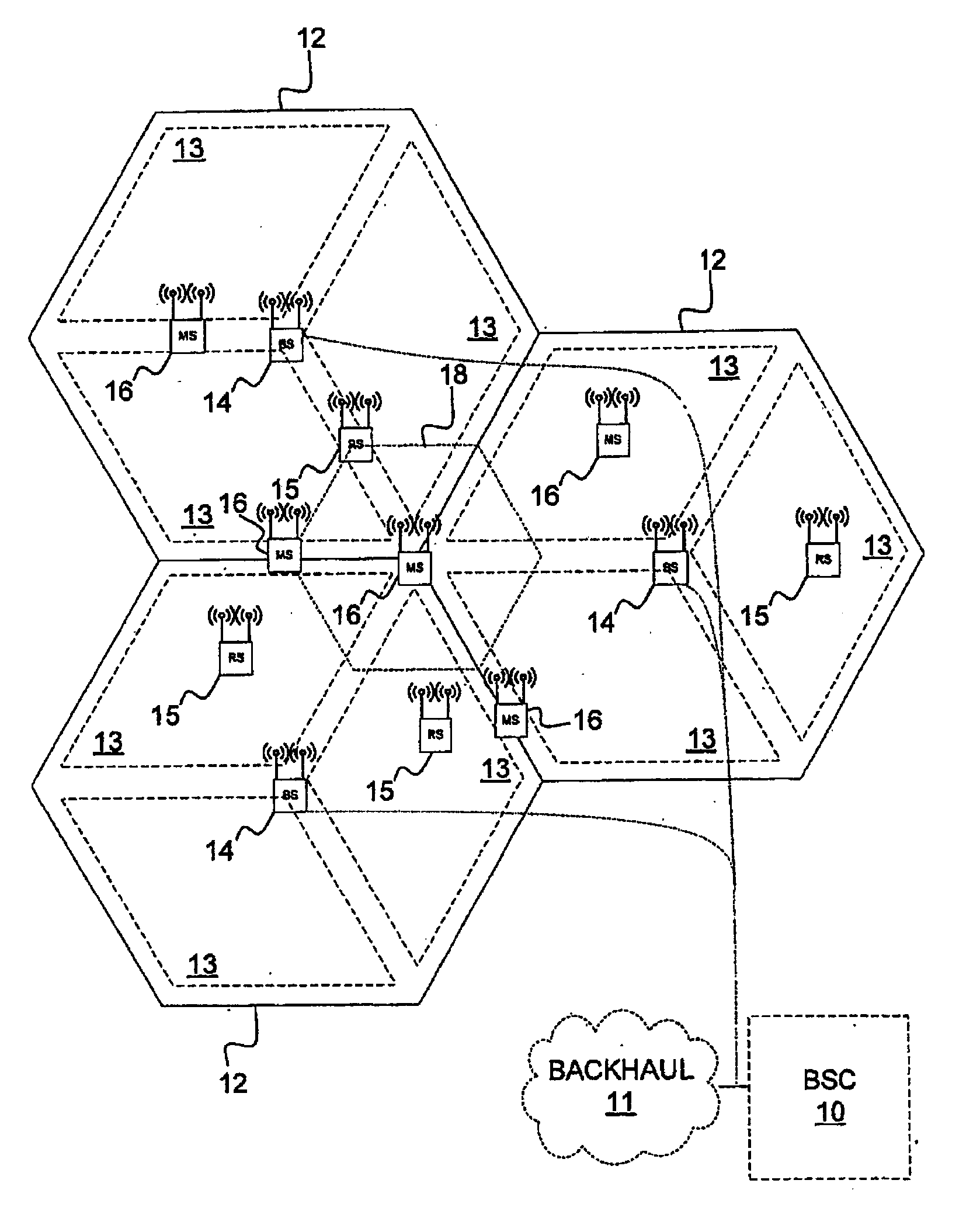
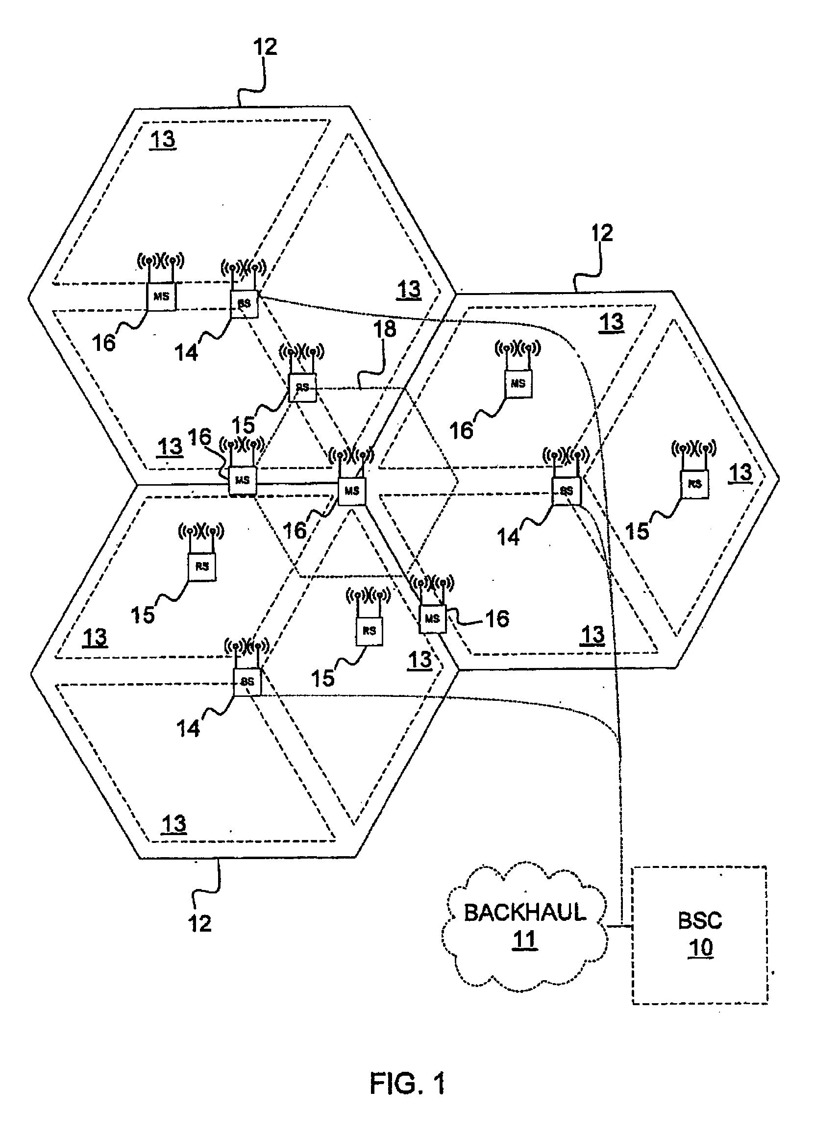
[0043]Referring now to the drawing figures in which like reference designators refer to like elements, FIG. 1 shows a base station controller (BSC) 10 which controls wireless communications within multiple cells 12, which cells are served by corresponding base stations (BS) 14. In some configurations, each cell is further divided into multiple sectors 13 (not shown). In general, each base station 14 facilitates communications using OFDM with mobile terminals 16, which are within the cell 12 associated with the corresponding base station 14. The movement of the mobile terminals 16 in relation to the base stations 14 results in significant fluctuation in channel conditions. As illustrated, the base stations 14 and mobile terminals 16 may include multiple antennas to provide spatial diversity for communications. As described in more detail below, relay stations 15 may assist in communications between base stations 14 and mobile terminals 16. Mobile terminals 16 can be handed off 18 fro...


PUM


Abstract

In a method of transmitting a data stream from a transmitter in a multiple-input-multiple-output (MIMO) wireless communication system, where the transmitter comprises a plurality of transmit antennas, a discrete Fourier transform (DFT) is applied to the data stream to generate a plurality of symbol sequences; symbols of a first symbol sequence from the plurality of symbol sequences are paired with symbols of a second symbol sequence from the plurality of symbol sequences to generate a plurality of symbol pairs, wherein the pairing results in an orphan symbol; a space-time block code (STBC) is applied to the symbol pairs to generate a plurality of sets of STBC symbols, each set of STBC symbols being associated with a corresponding one of the plurality of antennas; a cyclic delay diversity (CDD) operation is applied to the orphan symbol to generate a plurality of CDD symbols, each CDD symbol being associated with a corresponding one of the plurality of antennas; and each one of the antennas transmits the corresponding set of STBC symbols and the corresponding CDD symbol.

Description

RELATED APPLICATIONS[0001]This application claims the benefit of U.S. Provisional Patent Application No. 61 / 244,126, filed on Sep. 21, 2009, the contents of which are incorporated by reference herein.FIELD OF THE INVENTION[0002]The present invention relates to wireless communications and more particularly to methods and systems for providing transmit diversity and channel estimation for uplink transmissions.BACKGROUND[0003]Wireless communication systems are widely deployed to provide various types of communication content such as voice, data, and other content. These systems may be multiple-access systems capable of simultaneously supporting communication for multiple wireless terminals by sharing the available transmission resources (e.g., frequency channel and / or time interval). Since the transmission resources are shared, efficient allocation of the transmission resources is important as it impacts the utilization of the transmission resources and the quality of service perceived...

Claims


Application Information

Patent Timeline
Patent Type & Authority Applications(United States)
IPC IPC(8): H04B7/06
CPCH04B7/0667H04L27/2601H04B7/0671H04B7/0669H04L1/0625H04B7/0413H04L1/0668
Inventor JIA, MINGEBRAHIMI TAZEH MAHALLEH, MASOUDBALIGH, MOHAMMADHADIXU, HUAMA, JIANGLEIKHANDANI, AMIR
Owner NORTEL NETWORKS LTD
Why Eureka
Try Eureka