Vehicular shift control apparatus

a technology of shift control and control apparatus, which is applied in the direction of gearing control, gearing element, belt/chain/gearring, etc., can solve the problem that the above-described electrically operated actuator cannot be operated, and the vehicle may have a failure, so as to prevent discomfort

Active Publication Date: 2012-12-06
TOYOTA JIDOSHA KK
View PDF3 Cites 10 Cited by
  • Summary
  • Abstract
  • Description
  • Claims
  • Application Information

AI Technical Summary

Benefits of technology

[0015]According to a further preferred form of the invention, (a) the vehicle shift control apparatus inhibits the operation of the above-described actuator if the determination that the above-described actuator is inoperable is obtained in the above-described failure diagnosis, and (b) the shift control apparatus cancels an inhibition of the operation of the above-described actuator, before permitting the operation of the actuator after the inhibition if above-described vehicle shift control apparatus permits after the operation of above-described actuator is inhibited. In this preferred form of the invention, it is possible to avoid commanding the above-described actuator to be operated when the actuator is inoperable. In addition, it is possible to avoid a complicated control of permitting and inhibiting the operation of the above-described actuator.

Problems solved by technology

The vehicle may have a failure that disables the above-described electrically operated actuator to be operated, after the power application to the SBW control apparatus after the power removal therefrom, for instance.
Possible causes for such a failure of the vehicle include a failure of the electrically operated actuator per se, and a drop of a supply voltage to the electrically operated actuator below a lower limit value above which the electrically operated actuator is operable.
However, the SBW control apparatus is not configured to perform the normal control in the above-indicated case, but is configured to maintain the determination that the actuator is still inoperable.
In this respect, it is noted that this problem is not recognized in the prior art.

Method used


Image

  • Vehicular shift control apparatus
  • Vehicular shift control apparatus
  • Vehicular shift control apparatus

Examples


embodiment

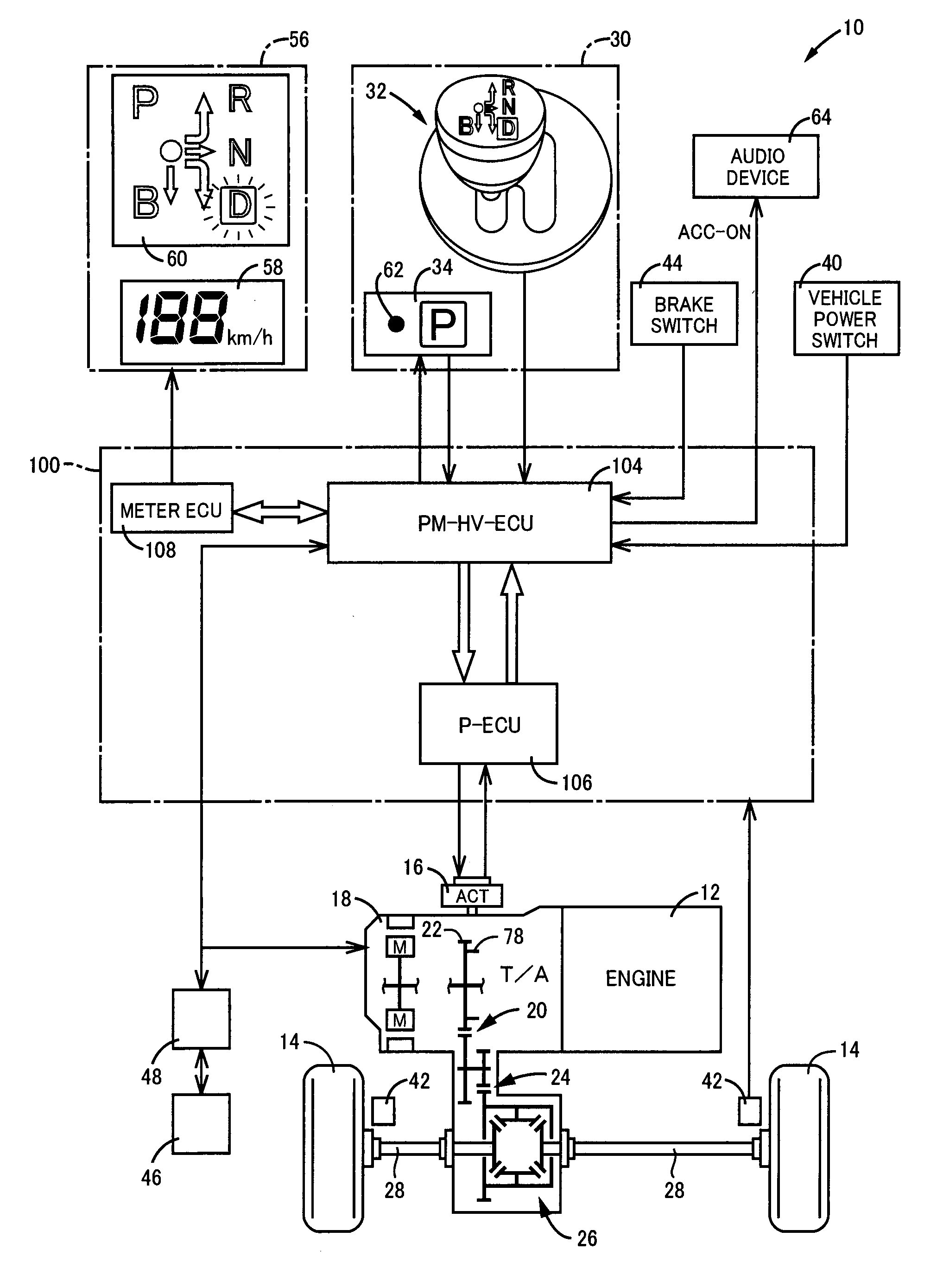
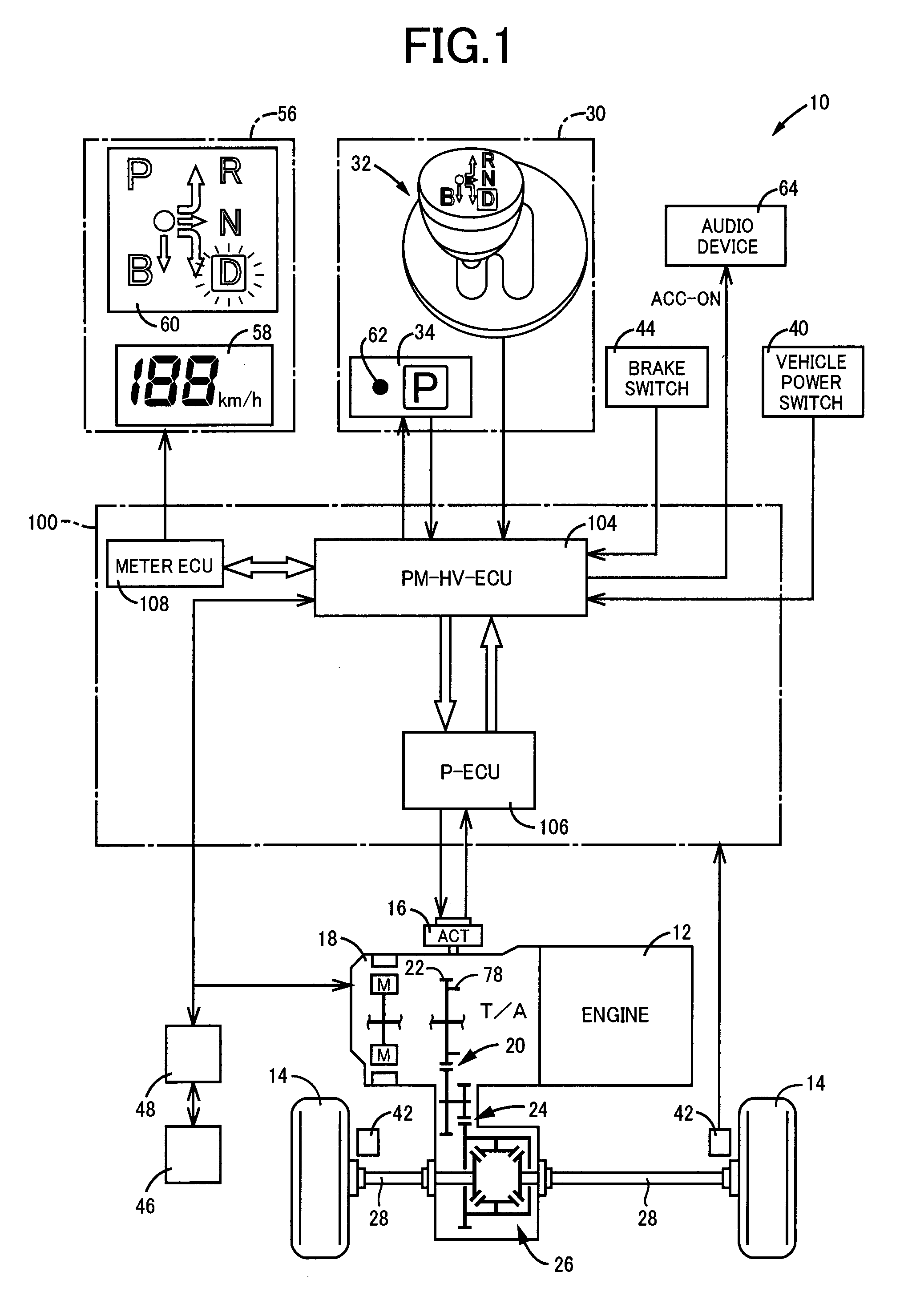
[0034]FIG. 1 is the view schematically showing an arrangement of a power transmitting path from an engine 12 of a vehicle 10 to which the present invention is applicable, to drive wheels 14 of the vehicle 10, and is also the block diagram showing major elements of a control system provided on the vehicle 10 to control a parking lock device 16 and other devices. As shown in FIG. 1, the vehicle 10 is provided with the parking lock device 16, a transmission 18, and a manually operable shift operating device 30, and adopts a shift-by-wire (SBW) system configured to electrically change a shift position associated with a manner of running of the vehicle 10, that is, a shift position (shift range) of the transmission 18. The transmission 18 is arranged so as to be suitably used on a transverse FF (front-engine front-drive) type of vehicle 10, so that a drive force of the engine 12 which is a vehicle drive power source in the form of an internal combustion engine is transmitted from an outp...


PUM


Abstract

A vehicular shift control apparatus for a vehicle provided with a parking lock device selectively switched to a locking position in which rotation of wheels of the vehicle is prevented and a non-locking position in which the rotation of the wheels is not prevented, by an operation of an electrically operated actuator, the vehicular shift control apparatus being configured to perform a failure diagnosis to determine whether the actuator is operable or not, the vehicular shift control apparatus includes: the vehicular shift control apparatus permits the operation of the actuator if a supply voltage to the actuator is raised from a value lower than a predetermined threshold supply voltage value to a value not lower than the threshold supply voltage value after a determination that the actuator is inoperable is obtained in the failure diagnosis.

Description

TECHNICAL FIELD[0001]The present invention relates to a control performed to deal with a failure of a shift-by-wire system.BACKGROUND ART[0002]There is well known a vehicular shift control apparatus adopting a so-called “shift-by-wire (SBW) system configured to electrically change a shift position associated with a manner of running of a vehicle, by operating an electrically operated actuator such as an electric motor. Patent Document 1 discloses an example of a SBW control apparatus provided in a shift range switching device. This SBW control apparatus is configured such that in the event of power application to the SBW control apparatus after instantaneous power removal therefrom, a position of an output shaft (an angular position of the output shaft) of the above-described electrically operated actuator, which output shaft position is memorized before the instantaneous power removal and kept in memory after the power removal is recognized as the output shaft position after the po...

Claims


Application Information

Patent Timeline
Patent Type & Authority Applications(United States)
IPC IPC(8): B60W10/184
CPCF16H2061/1292F16H61/12F16H2061/1288F16H63/483F16H63/3491Y10T477/644Y10T477/833Y10T477/81F16H63/3466
Inventor KANAI, OSAMUTSUTSUMI, TAKAHIKOKITAORI, ICHIROSUZUKI, TOSHINARIENDO, HIROATSUUENO, KOKISEKIYA, KEISUKE
Owner TOYOTA JIDOSHA KK
Why Eureka
Try Eureka