Vehicle braking system

a technology for braking systems and vehicles, applied in braking systems, braking components, transportation and packaging, etc., can solve problems such as large request of braking force to the whole vehicle, complicated control, and undesirable to maintain a uniform electric braking for

Active Publication Date: 2018-06-07
TOYOTA JIDOSHA KK
View PDF2 Cites 12 Cited by
  • Summary
  • Abstract
  • Description
  • Claims
  • Application Information

AI Technical Summary

Benefits of technology

[0004]However, in the braking system described in JP 11-147458 A, when a braking force required to the electric braking device changes, it is necessary to repeatedly maintain the braking force and release the braking force frequently so as to follow the change, which complicates the control. Accordingly, the braking system has room for improvement to perform the control of the electric brake more easily. The present disclosure provides a vehicle braking system enabling an easier control of an electric braking device.
[0006]According to the vehicle braking system in the aspect of the present disclosure, it is possible to restrain power consumption of the electric braking device by the operation of the mechanism configured to prohibit the retreat of the piston, and to appropriately generate a braking force required to the whole vehicle at that time by the control of the braking force of the hydraulic braking device. As a result, the vehicle braking system of the present disclosure serves as a system having a high practicability.
[0022]The above configuration is an effective aspect for power saving of the electric braking device in the state where the vehicle stops. The “braking force requested to the electric braking device to maintain the stop state of the vehicle (also referred to as a “vehicle hold achievable electric braking force” occasionally)” in the present term may be a braking force set such that the stop state of the vehicle can be maintained only by the electric braking force, or may be a braking force set such that the stop state of the vehicle can be maintained by a specific hydraulic braking force on the premise that such a specific hydraulic braking force exists. For example, in the electric braking force maintaining control at the time when the vehicle stops, in the former case, it is not necessary to generate a hydraulic braking force, and in the latter case, it is necessary to generate only some hydraulic braking force. According to the present aspect, by controlling the hydraulic braking force as such, it is possible to achieve power saving in the hydraulic braking device.
[0031]The so-called “anti-lock control (also referred to as an “anti-skid control” occasionally)” is a control to cancel a slip state when the wheels are locked to enter the slip state, and a braking force to the wheels thus locked is limited. Accordingly, it is preferable to stop the electric braking force maintaining control in which the maintaining electric braking force is kept generated by the electric braking device. The present aspect is an aspect in consideration of such a case. It may be preferable to perform the anti-lock control in emergency. Further, it is desirable to restore the normal control based on a sign before the anti-lock control is started. Generally, the anti-lock control is started such that a difference between an actual wheel rotation speed and an estimated wheel rotation speed, which is estimated from a vehicle running speed, is taken as a parameter, and when the parameter exceeds a given threshold, the anti-lock control is started. Accordingly, in the present aspect, for example, when the parameter exceeds another threshold set smaller than the above threshold, the electric braking force maintaining control is switched to the normal control, so that the switching can be performed without being late for the start of the anti-lock control.
[0041]According to the configuration of the present term, the piston retreat prohibition mechanism can maintain the electric braking force at the maintaining electric braking force without the energy supply from outside, which makes it possible to build an energy-saving system. The “one-way clutch mechanism” in the present term is a mechanism configured to permit only an operation in one direction out of two directions opposite to each other. As the “one-way clutch mechanism,” a ratcheting mechanism constituted by ratchet teeth and a lug may be employed.

Problems solved by technology

However, in the braking system described in JP 11-147458 A, when a braking force required to the electric braking device changes, it is necessary to repeatedly maintain the braking force and release the braking force frequently so as to follow the change, which complicates the control.
However, in a case where automatic driving or the like is performed, for example, they are not necessarily determined based on the operation of the brake operating member.
In a case where such a change occurs, it might be undesirable to maintain a uniform electric braking force.
During a vehicle running, the request of the braking force to the whole vehicle is particularly large.
Accordingly, differently from the normal control, it is difficult to generate an electric braking force corresponding to the request whole braking force that changes, by the control of the electric braking device.

Method used


Image

  • Vehicle braking system
  • Vehicle braking system
  • Vehicle braking system

Examples


Embodiment Construction

[0058]The following describes details of a vehicle braking system according to an embodiment as a mode for carrying out the present disclosure with reference to the drawings, and also describes modifications of the vehicle braking system. Note that the present disclosure can be performed in various modes including various alterations and modifications made based on knowledge of a person skilled in the art, in addition to the modes described in SUMMARY as well as the following embodiment and modifications.

[0059][A] Summary of Vehicle Drive System and Vehicle Braking System

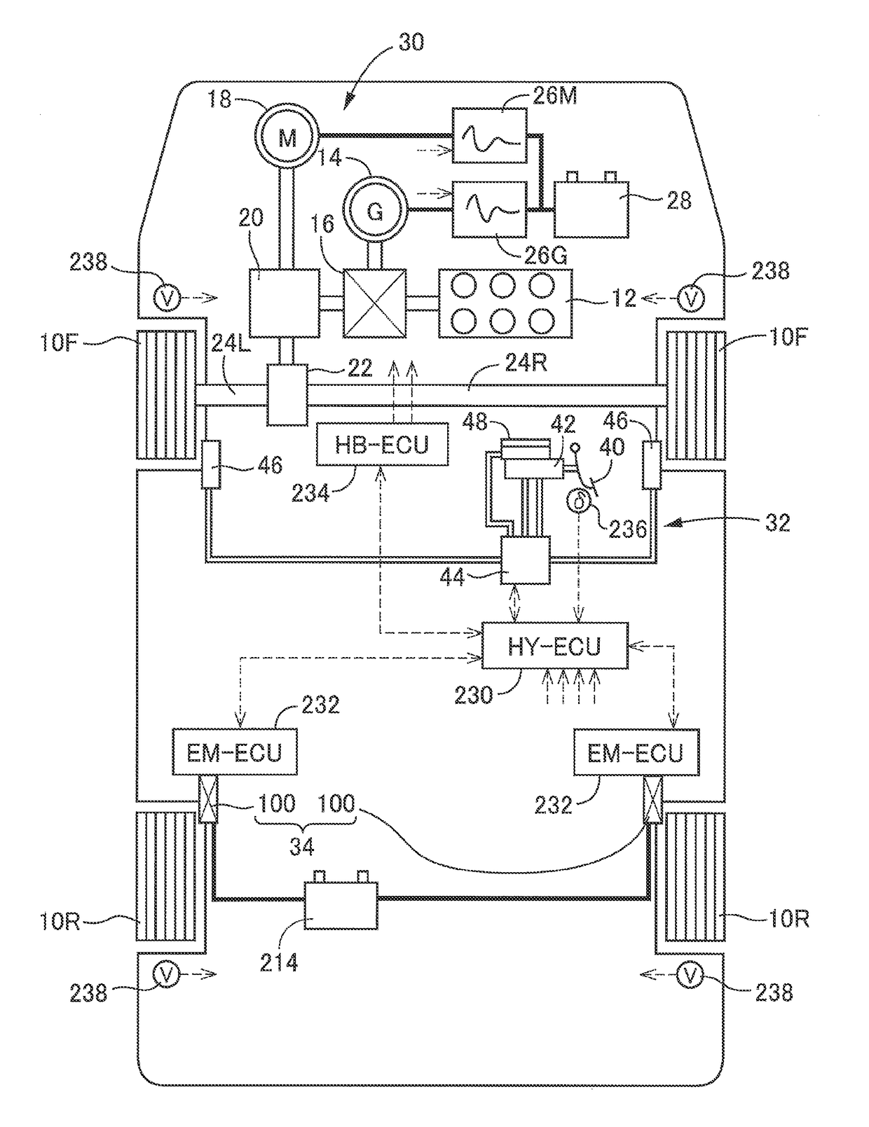
[0060]A vehicle provided with a vehicle braking system of the embodiment is a hybrid vehicle including two front wheels 10F and two rear wheels 10R, as schematically illustrated in FIG. 1, and the two front wheels 10F serve as driving wheels. First described is a vehicle drive system. The vehicle drive system provided in the vehicle includes an engine 12 as a drive source, a generator 14 mainly functioning as an ele...


PUM


Abstract

A brake control device is configured such that a hydraulic braking device is provided for one of a front wheel and a rear wheel, and an electric braking device is provided for the other one of them. The electric braking device is provided with a mechanism configured to prohibit retreat of a piston for pressing friction members against a rotor that rotates with the wheel. The brake control device is configured to maintain, by an operation of the mechanism, a braking force that does not depend on a force of an electric motor as a drive force and to control a braking force generated by the hydraulic braking device based on a difference between the braking force thus maintained and a braking force requested for the electric braking device.

Description

INCORPORATION BY REFERENCE[0001]The disclosure of Japanese Patent Application No. 2016-235253 filed on Dec. 2, 2016 including the specification, drawings and abstract is incorporated herein by reference in its entirety.BACKGROUND1. Technical Field[0002]The present disclosure relates to a vehicle braking system. More particularly, the present disclosure relates to a vehicle braking system including an electric braking device for generating a braking force depending on a force of an electric motor.2. Description of Related Art[0003]In a vehicle braking system including an electric braking device for generating a braking force depending on a force of an electric motor, the following technique has been considered as described in Japanese Patent Application Publication No. 11-147458 (JP 11-147458 A), for example: when a set condition is satisfied, a braking force generated by the electric braking device is maintained at a predetermined magnitude without depending on the force of the elec...

Claims


Application Information

Patent Timeline
Patent Type & Authority Applications(United States)
IPC IPC(8): B60T8/26F16D65/18B60T8/176B60T7/04B60T13/74B60T8/172B60L7/18B60L7/26
CPCB60T8/26F16D65/18B60T8/176B60T7/042B60T13/741B60T13/746B60T8/172B60L7/18B60L7/26F16D2121/04F16D2121/24F16D2125/36F16D2125/40F16D2125/50F16D2127/06F16D2129/10B60T2270/604B60T13/745F16D55/226F16D65/14F16D2123/00B60T1/10B60T8/267B60T8/4081B60T13/146B60T13/662B60T13/686B60L50/16F16D61/00Y02T10/7072B60T8/00
Inventor TAKAHASHI, AKIHIROSHIBATA, KOHJI
Owner TOYOTA JIDOSHA KK
Why Eureka
Try Eureka