

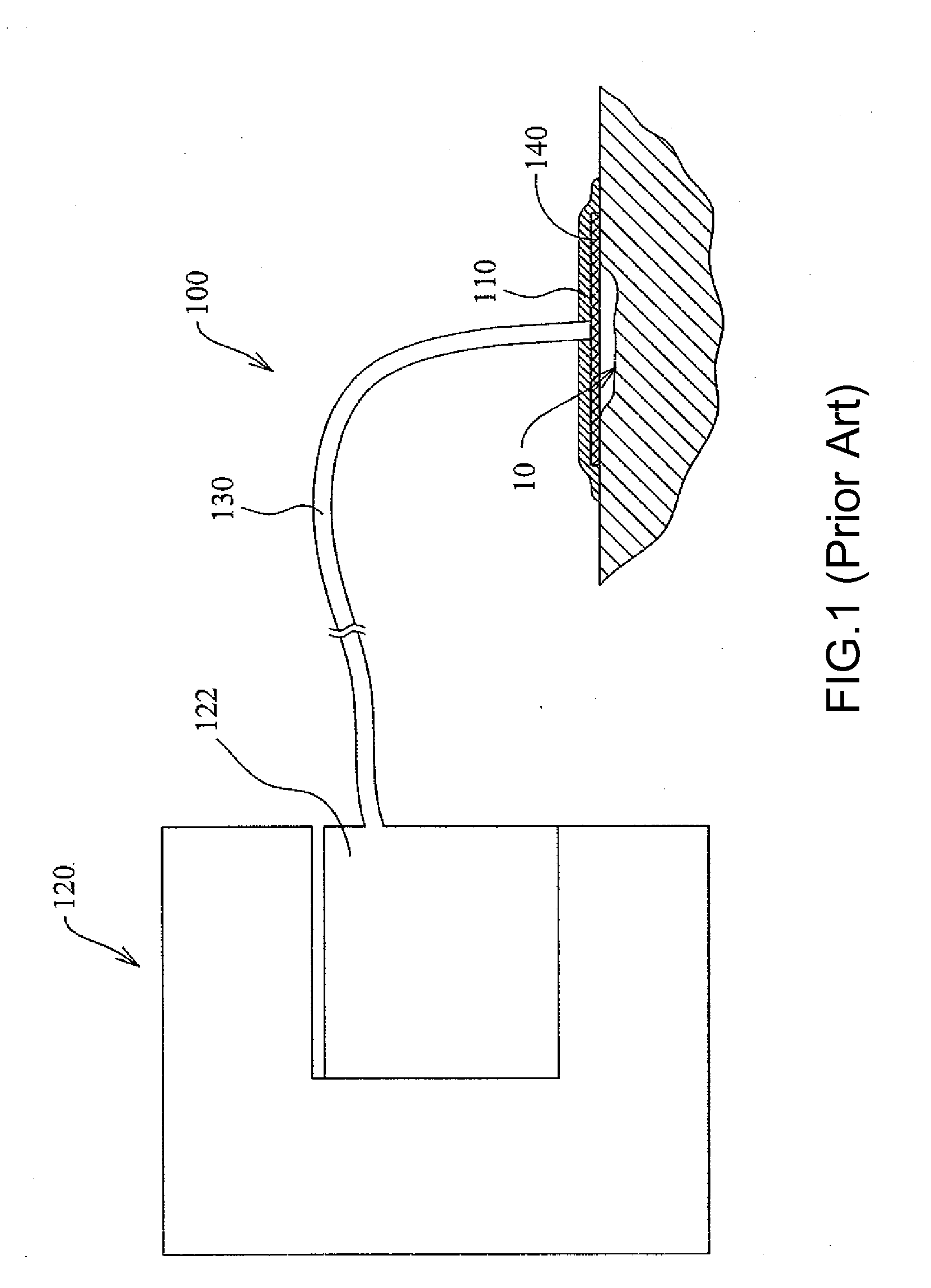
Wound drainage equipment, conduit, connector and wound cover
- Summary
- Abstract
- Description
- Claims
- Application Information
AI Technical Summary
Benefits of technology
Problems solved by technology
Method used
Image

Examples
first embodiment
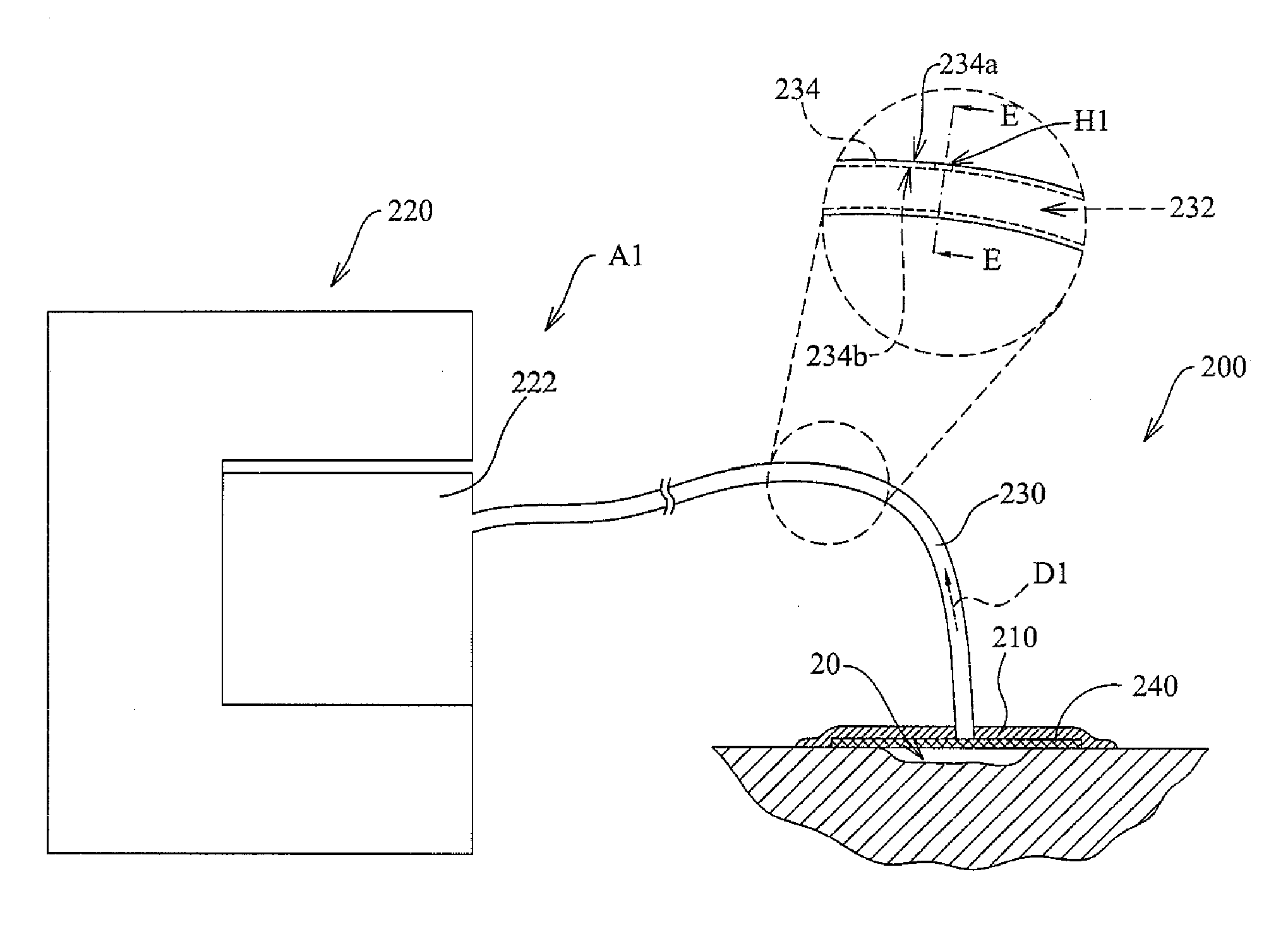
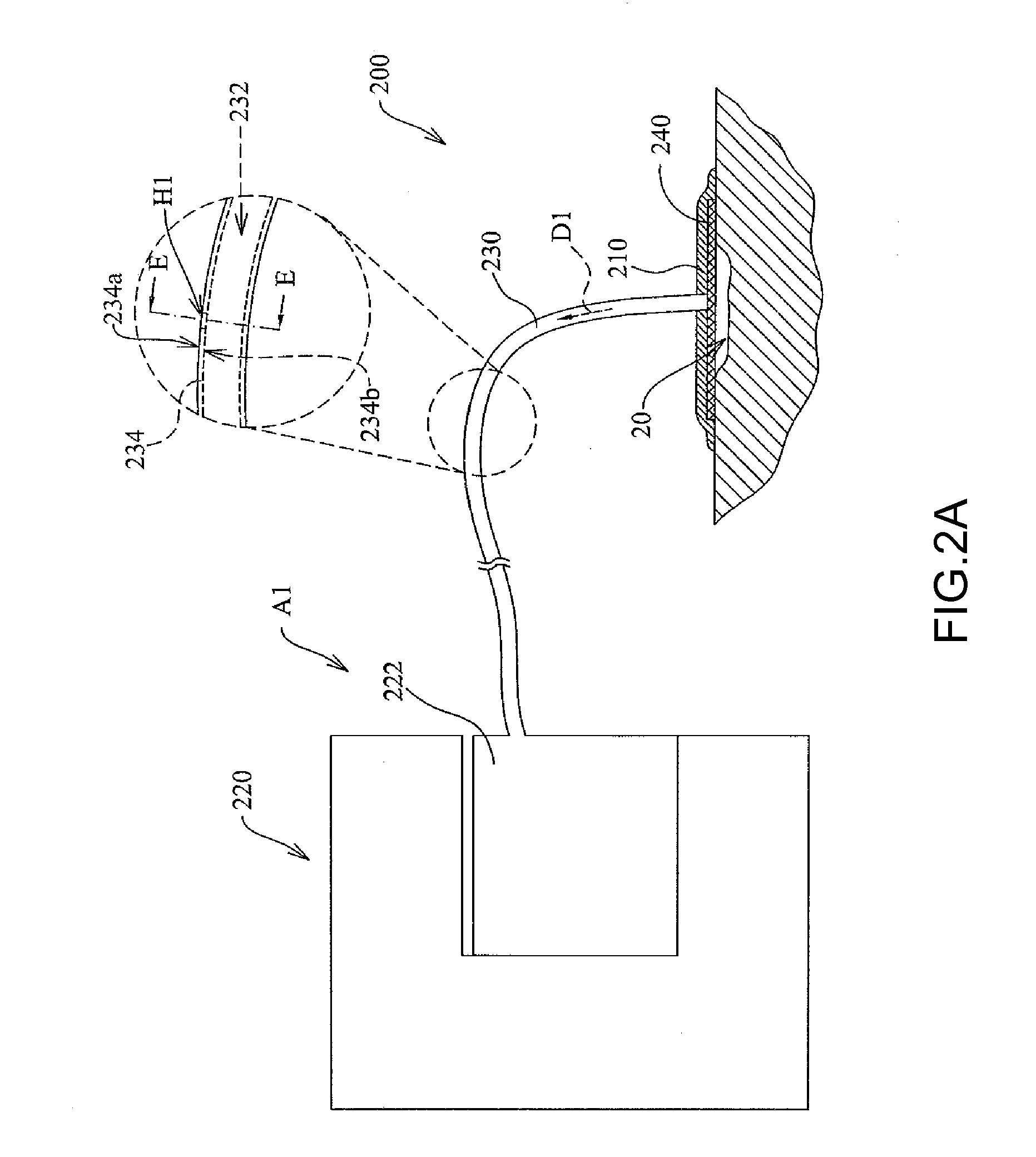
[0043]FIG. 2A is a schematic view of a wound drainage equipment according to the first embodiment of the present invention. FIG. 2B is a cross-sectional schematic view of a conduit taken along line EE of FIG. 2A. Referring to FIG. 2A and FIG. 2B, a wound drainage equipment 200 in this embodiment is adapted for sucking exudates in a wound 20. The wound drainage equipment 200 comprises a wound drainage assembly A1 and at least one aeration hole H1. The wound drainage assembly A1 comprises a wound cover 210, a suction appliance 220, a conduit 230, and a porous screen 240.
[0044]The porous screen 240 is adapted for being disposed at the wound 20. The wound cover 210 is adapted for being disposed on the porous screen 240 and the wound 20. In this embodiment, the porous screen 240 is a foam-style substance which is made of polyurethane (PU) or polyvinyl alcohol (PVA) and is capable of absorbing water and is porous structure. The porous screen 240 can also be gauze. In this embodiment, the ...
second embodiment
[0049]FIG. 3 is an exploded schematic view of a conduit according to the second embodiment of the present invention. Referring to FIG. 3, a conduit 330 of this embodiment can be substituted for the conduit 230 of the first embodiment. The conduit 330 of this embodiment has a first tube body 330a, a second tube body 330b, and a connector 330c. The connector 330c is adapted for connecting the first tube body 330a and the second tube body 330b. An end of the first tube body 330a is opposite to the connector 330c and adapted for communicating with the wound 20 (shown in FIG. 2A). An end of the second tube body 330h is opposite to the connector330c and adapted to be connected to the collecting container 222 of the suction appliance 220 (shown in FIG. 2A). In this embodiment, an aeration hole H2 is disposed at the connector 330c.
third embodiment
[0050]FIG. 4 is a schematic view of a would drainage equipment according to the third embodiment of the present invention. Referring to FIG. 4, in this embodiment, an aeration hole H3 of a wound drainage equipment 400 is disposed at a wound cover 410 of a wound drainage assembly A3. The wound cover 410 is a cup-shaped cover. A lumen 432 of a conduit 430 communicates with the wound cover 410 and a collecting container 422 of a suction appliance 420 and thereby communicates with a wound 40 and the collecting container 422.
PUM
 Abstract
Description
Claims
Application Information