Device for assisting cesarean deliveries

a technology for assisting cesarean deliveries and fetal head removal, which is applied in the field of assisting cesarean deliveries, can solve the problems of difficulty in safely dislodging the impacted fetal head, and achieve the effects of facilitating the release of the impacted structure, enhancing the ability of the practitioner, and facilitating the removal of the fetal head

Inactive Publication Date: 2012-12-06
TUFTS MEDICAL CENTER INC
View PDF2 Cites 5 Cited by
  • Summary
  • Abstract
  • Description
  • Claims
  • Application Information

AI Technical Summary

Benefits of technology

[0009]A catheter is disclosed that advantageously facilitates release of a structure lodged within a body cavity by inserting a sterile irrigant between the structure and the body cavity so as to break a vacuum holding the structure within the body cavity. For example, in a cesarean delivery, the catheter is placed below the vertex at the time of delivery so as to provide a sterile irrigant between the fetal head and the maternal pelvis. Doing so breaks the vacuum holding the fetal head in the maternal pelvis and lavages the vertex upwards, permitting the practitioner to easily remove the fetal head from the pelvis, and complete the cesarean delivery.
[0010]In certain embodiments, the catheter includes a finger carrier disposed adjacent the leading end of the catheter, permitting the catheter to be finger mounted. This configuration further advantageously permits finger-directed placement of the catheter in the body cavity, allowing proper placement despite tight space requirements.
[0011]In certain embodiments, the catheter leading end is relatively wide and thin relative to the mid-section and proximal end of the catheter, facilitating insertion of the leading end into tight spaces between closely engaged structures.
[0012]In certain embodiments, the leading end is generally flat on a side opposed to the finger carrier. The flat side is provided with surface features configured to enhance the ability of the practitioner to engage the structure to be dislodged from the body cavity. For example, the flat side may include raised ridges configured to enhance the user's ability to grip the fetal scalp while withdrawing the fetal skull from the maternal pelvis. In addition, by providing improved finger grip, less finger flexion force is required to achieve an adequate grip, further reducing trauma to the fetal skull.

Problems solved by technology

The obstetrical challenge of the cesarean delivery after a long labor often includes difficulty in safely dislodging the impacted fetal head.

Method used


Image

  • Device for assisting cesarean deliveries
  • Device for assisting cesarean deliveries
  • Device for assisting cesarean deliveries

Examples


Embodiment Construction

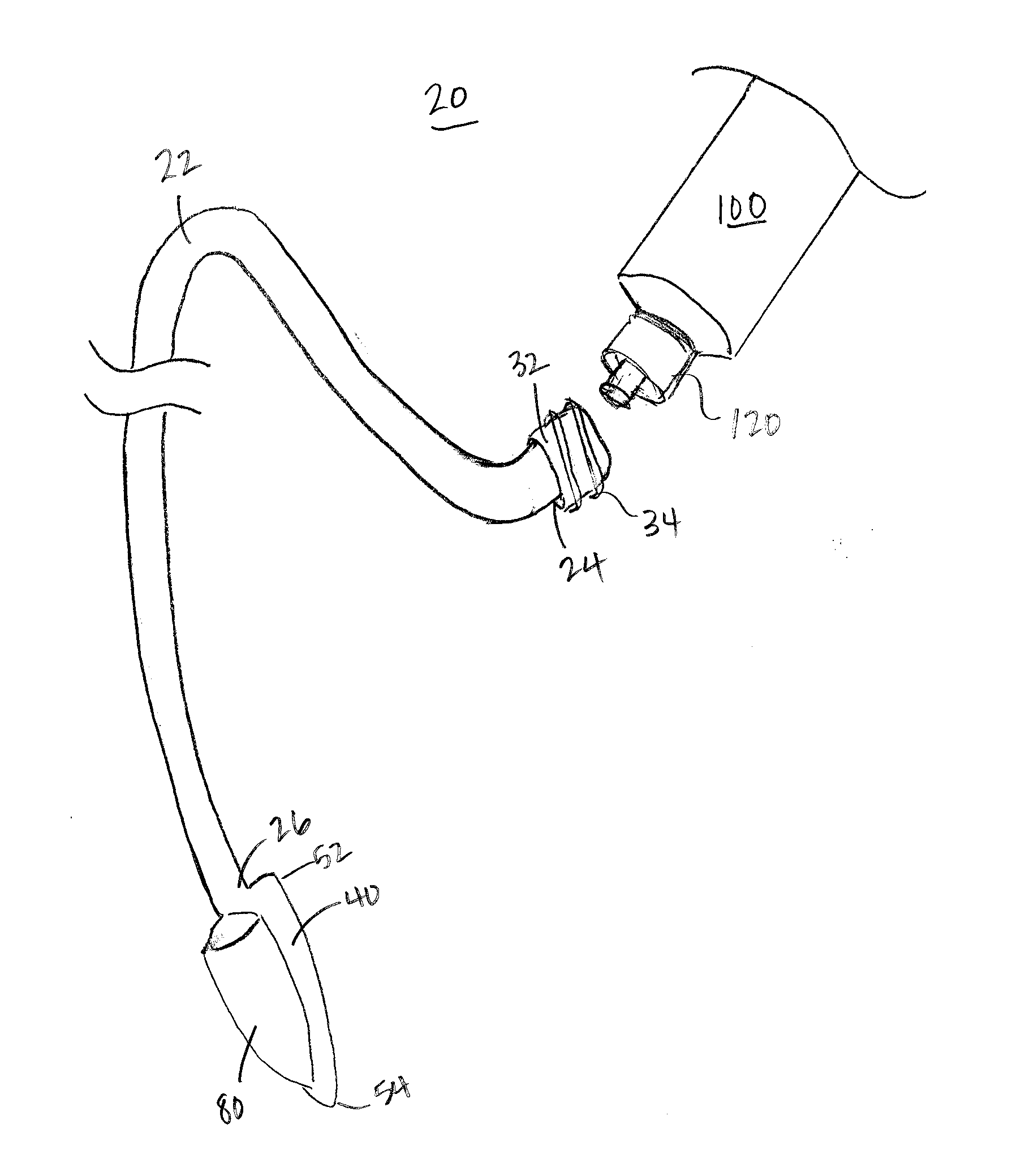
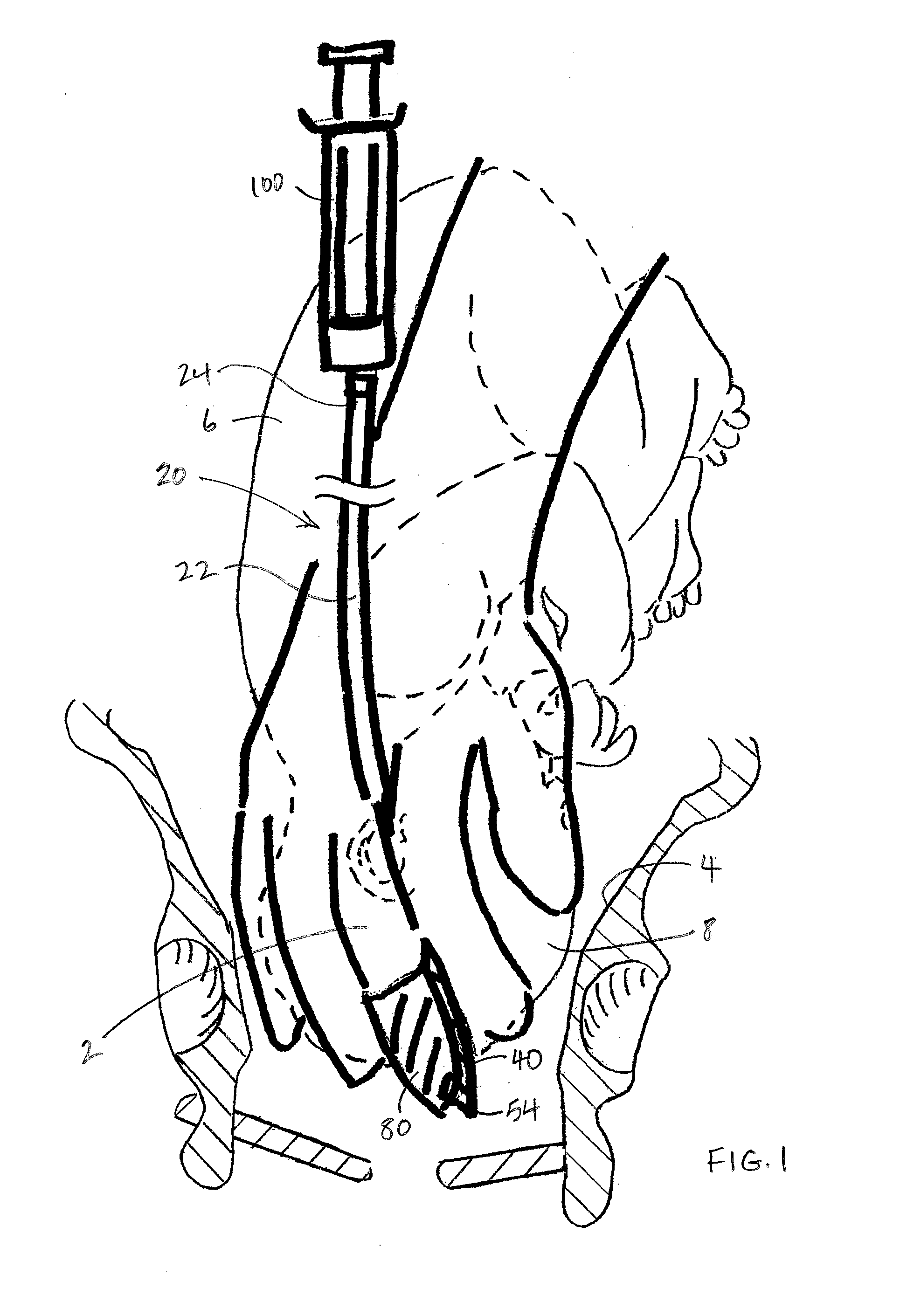
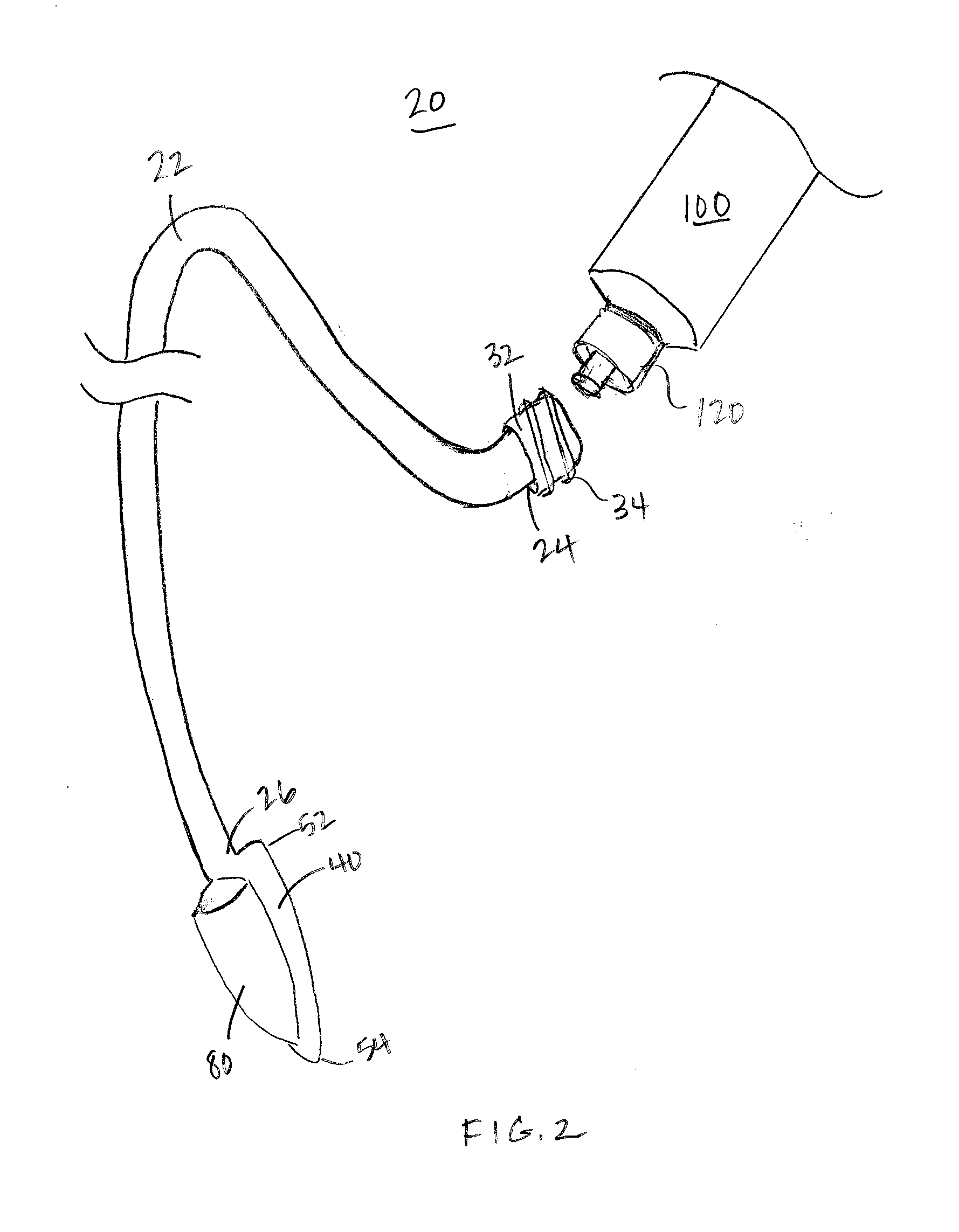
[0021]Referring now to FIGS. 1-3, the catheter device 20 includes a tubular portion 22 including a proximal end 24 configured to be secured to a fluid supply 100. The catheter device 20 includes a tip portion 40 that extends from a distal end 26 of the tubular portion, where the distal end 26 is opposed to the proximal end 24. In addition, an internal fluid passageway 30 extends from the proximal end 24 to a terminus 54 of the tip portion 40. As will be discussed in greater detail below, the tip portion 40 has a shape that is wide and flat relative to the tubular portion 22 to facilitate insertion of the catheter device 20 into tight spaces, and particularly between an object 8 and a body cavity surface 4 within which the object 8 is lodged. In addition, the tip portion 40 includes a carrier 80 so that the catheter device 20 can be mounted on, and directed by, a finger 2 during use, as also discussed further below.

[0022]Referring to FIG. 4, the tubular portion 22 has a circular cros...


PUM


Abstract

A catheter device for facilitating release of a structure lodged within a body cavity includes a flexible catheter and carrier configured to mount the catheter to a finger. The catheter includes a leading end having an opening configured to permit fluids within the catheter to exit the catheter, and a proximal end configured to connect to a fluid source. A method using the catheter device to release a fetal head from a maternal pelvis during cesarean delivery of the fetus is provided.

Description

CROSS REFERENCE TO RELATED APPLICATIONS[0001]This application claims the benefit of U.S. Provisional Application No. 61 / 493,620, titled “Device for Assisting Cesarean Deliveries” filed Jun. 6, 2011. The contents of the above application are incorporated herein by reference.BACKGROUND OF THE INVENTION[0002]The obstetrical challenge of the cesarean delivery after a long labor often includes difficulty in safely dislodging the impacted fetal head. While the occurrence of fetal cervical fracture during cesarean delivery is rare, fetal skull fracture and intracerebral hemorrhage, trauma to maternal tissues resulting in hemorrhage and bladder damage, and injury to the delivering obstetrician is not. As protracted labors and cesarean section rates rise, a simple but effective device to facilitate delivery is needed.SUMMARY[0003]In some aspects, a device is provided for facilitating release of a structure lodged within a body cavity. The device includes a flexible catheter having a leading ...

Claims


Application Information

Patent Timeline
Patent Type & Authority Applications(United States)
IPC IPC(8): A61B17/44
CPCA61B2017/00438A61B17/42A61B2218/002A61B2019/043A61B19/04A61B42/00A61B42/20
Inventor MCCUE, BRIGID KATHLEENNONNAMAKER, MATTHEW MCCUE
Owner TUFTS MEDICAL CENTER INC
Why Eureka
Try Eureka