
Thermal management systems and methods for auxiliary power units

Inactive Publication Date: 2012-12-13
HONEYWELL INT INC
View PDF4 Cites 30 Cited by
  • Summary
  • Abstract
  • Description
  • Claims
  • Application Information

AI Technical Summary

Benefits of technology

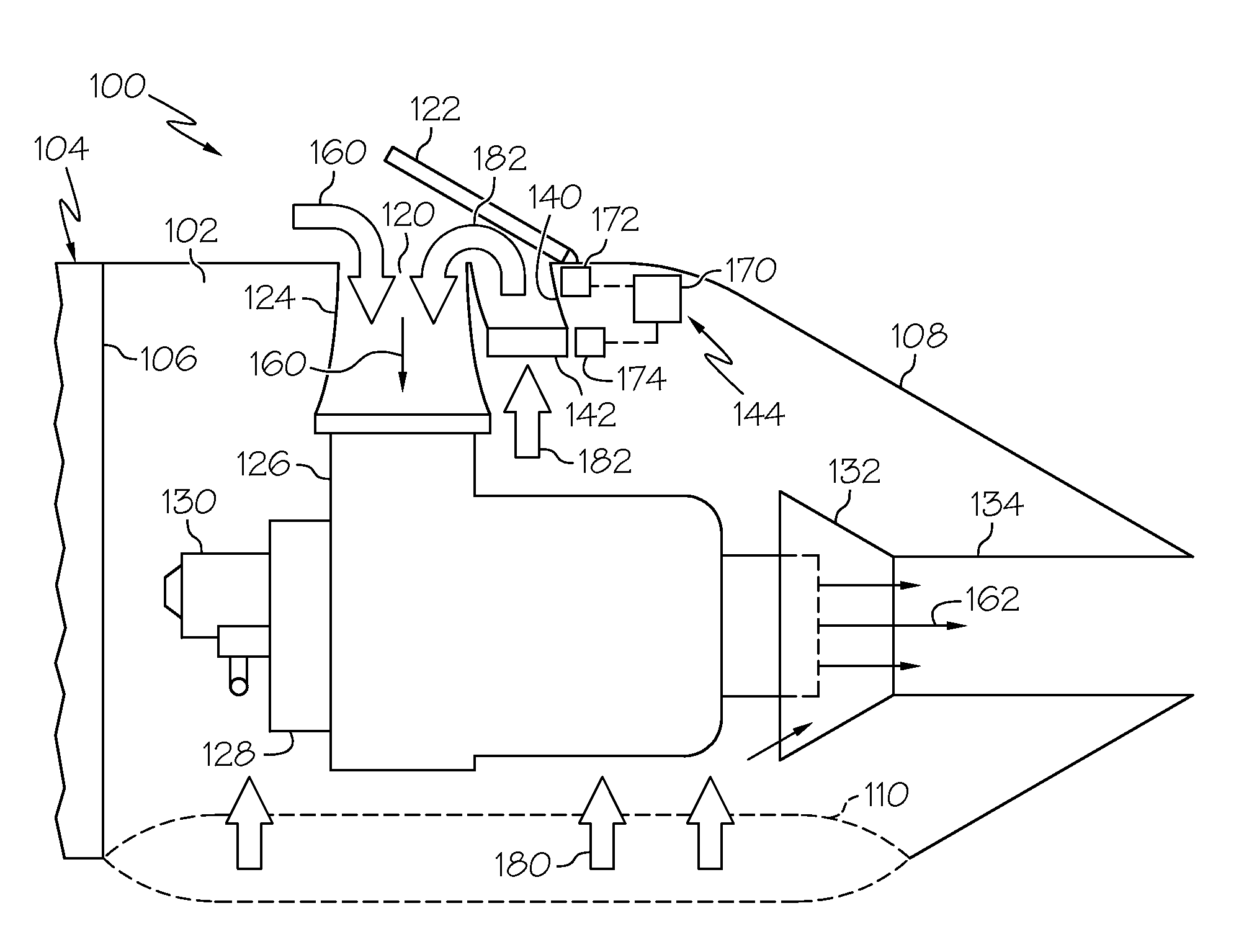
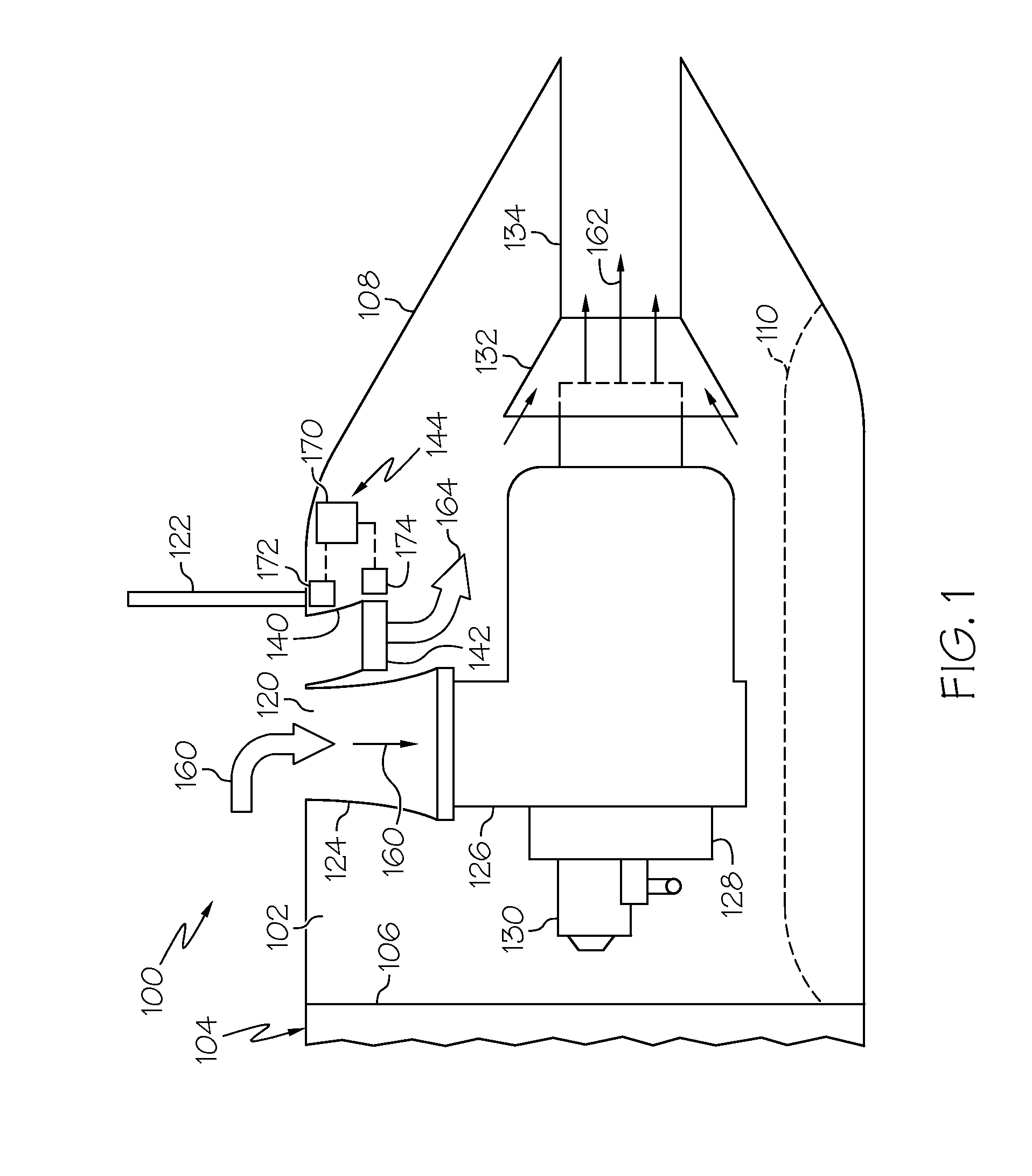
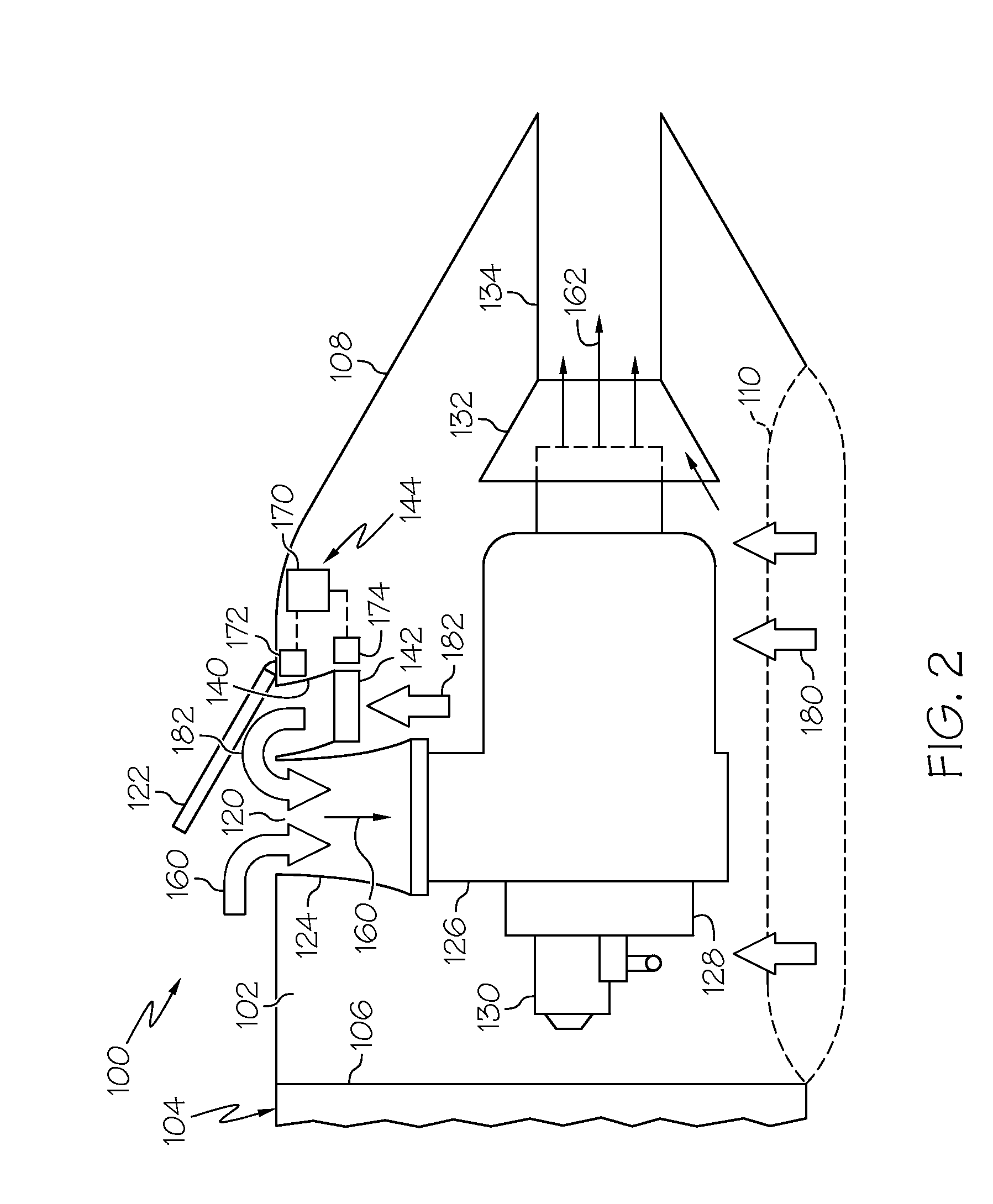
[0006]In accordance with an exemplary embodiment, an auxiliary power unit (APU) is provided and configured to be mounted in an APU compartment that defines an inlet opening. The APU includes a power section having components lubricated with oil; an intake duct coupled to the inlet opening and the power section and configured to direct a first portion of air flow through the inlet opening into the power section; an oil cooler coupled to the power section and configured to cool the

Problems solved by technology

However, at times, thermal management of the APU may be an issue, particularly during maintenance operations.
However, these techniques may not be sufficient to properly manage the temperature, may reduce APU performance or efficiency, or may have an adverse impact on the size and weight of the APU.

Method used


Image

  • Thermal management systems and methods for auxiliary power units
  • Thermal management systems and methods for auxiliary power units
  • Thermal management systems and methods for auxiliary power units

Examples


Embodiment Construction

[0013]The following detailed description is merely exemplary in nature and is not intended to limit the invention or the application and uses of the invention. Furthermore, there is no intention to be bound by any theory presented in the preceding background or the following detailed description.

[0014]Broadly, exemplary embodiments described herein provide thermal management systems and methods for maintaining a desired temperature in an auxiliary power unit (APU). Particularly, an intake duct and a cooling duct extend from the inlet opening at the exterior of the aircraft to respectively provide operating air to the power section of the APU and cooling air to the oil cooler of the APU. An inlet door may selectively open and close the inlet opening to adjust air flow characteristics of the intake duct and the cooling duct. During typical operation, the inlet door may be positioned at a first angle. However, during a maintenance operation in which compartment doors of the APU are ope...


PUM


Abstract

An auxiliary power unit (APU) is provided and configured to be mounted in an APU compartment that defines an inlet opening. The APU includes a power section having components lubricated with oil; an intake duct coupled to the inlet opening and the power section and configured to direct a first portion of air flow through the inlet opening into the power section; an oil cooler coupled to the power section and configured to cool the oil of the power unit; a cooling duct coupled to the oil cooler and the intake opening; an inlet door mounted at the inlet opening and configured to open and close the inlet opening, the inlet door further configured to be positioned in at least a first open position and a second open position; and a thermal management system configured to adjust the inlet door between the first open position and the second open position based on one or more operating temperatures within the APU.

Description

TECHNICAL FIELD[0001]The present invention generally relates to auxiliary power units (APUs), and more particularly relates to thermal management systems and methods for APUs.BACKGROUND[0002]Aircraft often have an on-board auxiliary power unit (APU) to provide electrical power and compressed air to various systems. As examples, when the aircraft is on the ground, the APU is the primary source of power to drive the environmental control systems, air driven hydraulic pumps, auxiliary generator, and the starters for the engines. During flight, the APU may provide pneumatic and electric power. Typically, the APU includes a compressor, a combustor, a turbine, and other components that are lubricated with oil cooled by an oil cooler.[0003]The APU is typically arranged in an APU compartment at the tailcone of an aircraft and receives operating and cooling air from the atmosphere through an inlet opening in the exterior surface of the tailcone. An intake duct defines an airflow passage betw...

Claims


Application Information

Patent Timeline
IPC IPC(8): B64D41/00F02C7/18F02C7/06F02C7/057
CPCF02C7/06F02C7/32F05D2220/50Y02T50/671B64D41/00B64D2041/002B64D33/10Y02T50/60
Inventor ERTZ, TIMOTHYGEYER, GREGORYNESDILL, THOMASMERKLEY, FRANK
Owner HONEYWELL INT INC
Learn More