Stator unit and motor

a technology of a stator unit and a motor, which is applied in the direction of magnetic circuit rotating parts, magnetic circuit shape/form/construction, windings, etc., can solve the problems of increasing the difficulty of ensuring a clearance between adjacent coils in a circumferential direction, and the amount of coil bulging becomes very large, so as to increase the number of coil turns

Active Publication Date: 2012-12-13
NIDEC CORP
View PDF13 Cites 22 Cited by
  • Summary
  • Abstract
  • Description
  • Claims
  • Application Information

AI Technical Summary

Benefits of technology

[0009]According to the first and second preferred embodiments of the present invention, in the vicinity of an inner peripheral portion of the tooth, bulging of the coil in a circumferential direction surrounding the central axis can be suppressed. For this reason, a clearance can be secured between adjacent coils, and as a result of this, the number of turns of the coil can be increased.

Problems solved by technology

However, as the number of turns of a coil is increased, it becomes more and more difficult to secure a clearance between coils that are adjacent to each other in a circumferential direction.
In particular, in a motor having an insulator, an amount of bulging of the coils becomes very large.

Method used


Image

  • Stator unit and motor
  • Stator unit and motor
  • Stator unit and motor

Examples


Embodiment Construction

[0028]Hereinafter, exemplary preferred embodiments of the present invention will be described with reference to the drawings.

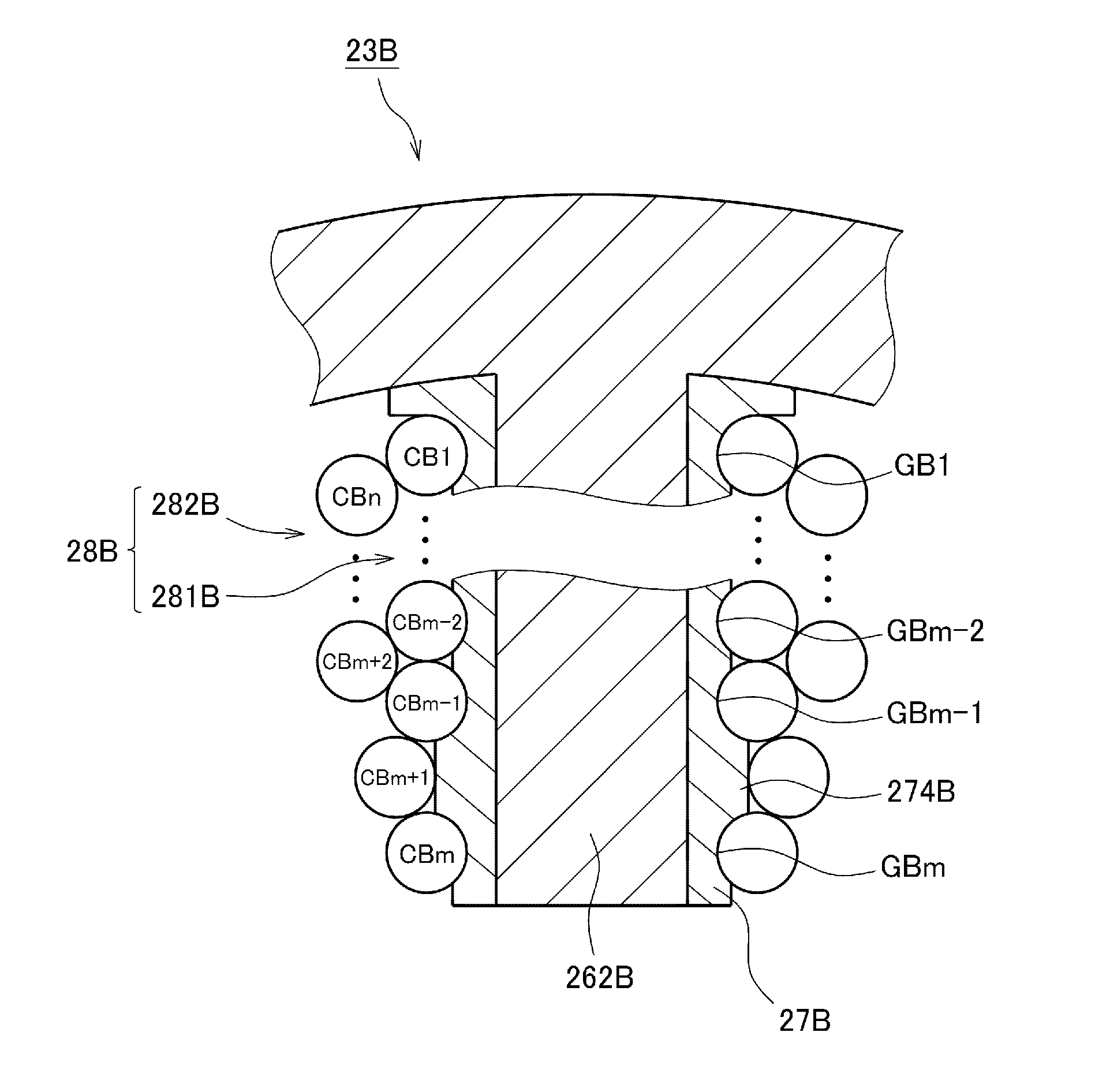
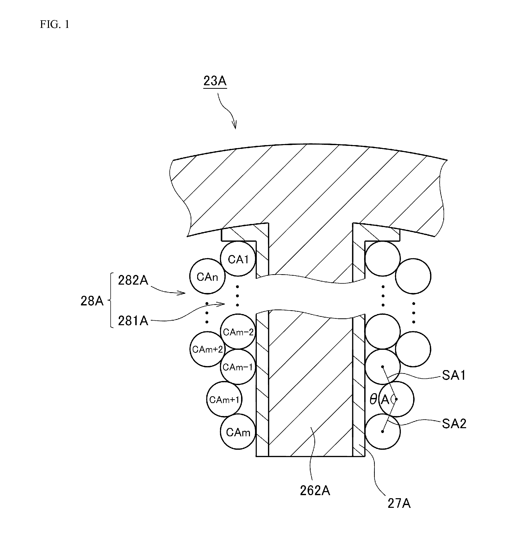
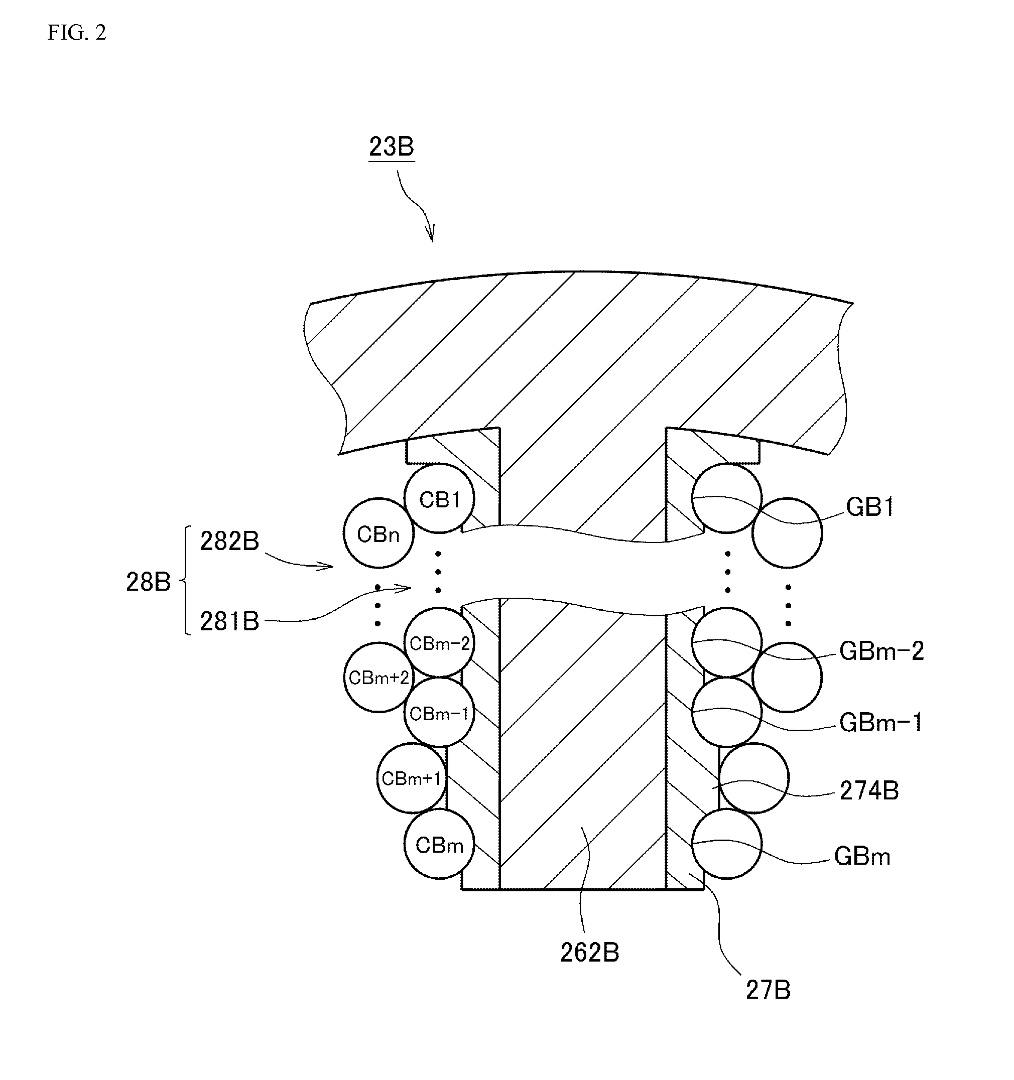
[0029]FIG. 1 is a partial cross-sectional view of a stator unit 23A related to a first preferred embodiment of the present invention. The stator unit 23A is provided with a plurality of teeth 262A each extending in a radial direction with respect to the central axis. In FIG. 1, the cross-sections perpendicular to the central axis of one of the teeth 262A and portions in the vicinity thereof are shown. Each of teeth 262A is covered by an insulator 27A. Further, a conducting wire is wound around the insulator 27A, so that a coil 28A is provided.

[0030]Here, m is set to be an integer of 2or more and n is set to be an integer larger than m+1. As shown in FIG. 1, the coil 28A includes a first layer 281A defined by a first turn CA1 to an m-th turn CAm, and a second layer 282A defined by an m+1-th turn CAm+1 to an n-th turn CAn. The first turn CA1 to the m-th turn CAm...


PUM


Abstract

A stator unit including a coil in which a distance between an m−1-th turn and an m-th turn is wider than each distance in a first turn to the m−1-th turn. The m+1-th turn is disposed between the m−1-th turn and the m-th turn. Further, in a cross-section perpendicular to a central axis and passing a tooth, an angle between a line segment connecting respective centers of the m+1-th turn and the m−1-th turn and a line segment connecting respective centers of the m+1-th turn and the m-th turn is about 120° or more. With this structure, bulging in a circumferential direction of the coil adjacent to an inner peripheral portion of the tooth can be suppressed and a clearance can be secured between adjacent coils such that the number of turns of the coil can be increased.

Description

BACKGROUND OF THE INVENTION[0001]1. Field of the Invention[0002]The present invention relates to a stator unit and more specifically to a motor including a stator unit.[0003]2. Description of the Related Art[0004]In a conventional motor, a structure in which an insulator made of resin is mounted on a plurality of teeth extending radially with respect to a central axis and a conducting wire is wound around the insulator, thereby forming a coil is known. The insulator is interposed between the tooth and the coil, thereby electrically insulating both members from each other. A conventional motor having such an insulator is described in, for example, Japanese Unexamined Patent Application Publication No. 2007-267492.[0005]When designing a motor, there is a desire to increase the number of turns of a coil in order to enhance characteristics such as torque. However, as the number of turns of a coil is increased, it becomes more and more difficult to secure a clearance between coils that a...

Claims


Application Information

Patent Timeline
Patent Type & Authority Applications(United States)
IPC IPC(8): H02K3/34H02K3/12
CPCH02K2213/03H02K1/27H02K2203/12H02K3/18H02K3/522H02K3/345H02K3/28
Inventor HAGA, HIDEHIROADACHI, KUNIAKISHOJI, KENSUKEHATTORI, TAKASHIATARASHI, TAKAOAONO, MASATO
Owner NIDEC CORP
Why Eureka
Try Eureka