Lighting device, display device and television receiver
a technology of display device and light source, which is applied in the field of light source device, display device and television receiver, can solve the problems of uneven brightness and uneven light distribution
- Summary
- Abstract
- Description
- Claims
- Application Information
AI Technical Summary
Benefits of technology
Problems solved by technology
Method used
Image
Examples
first embodiment
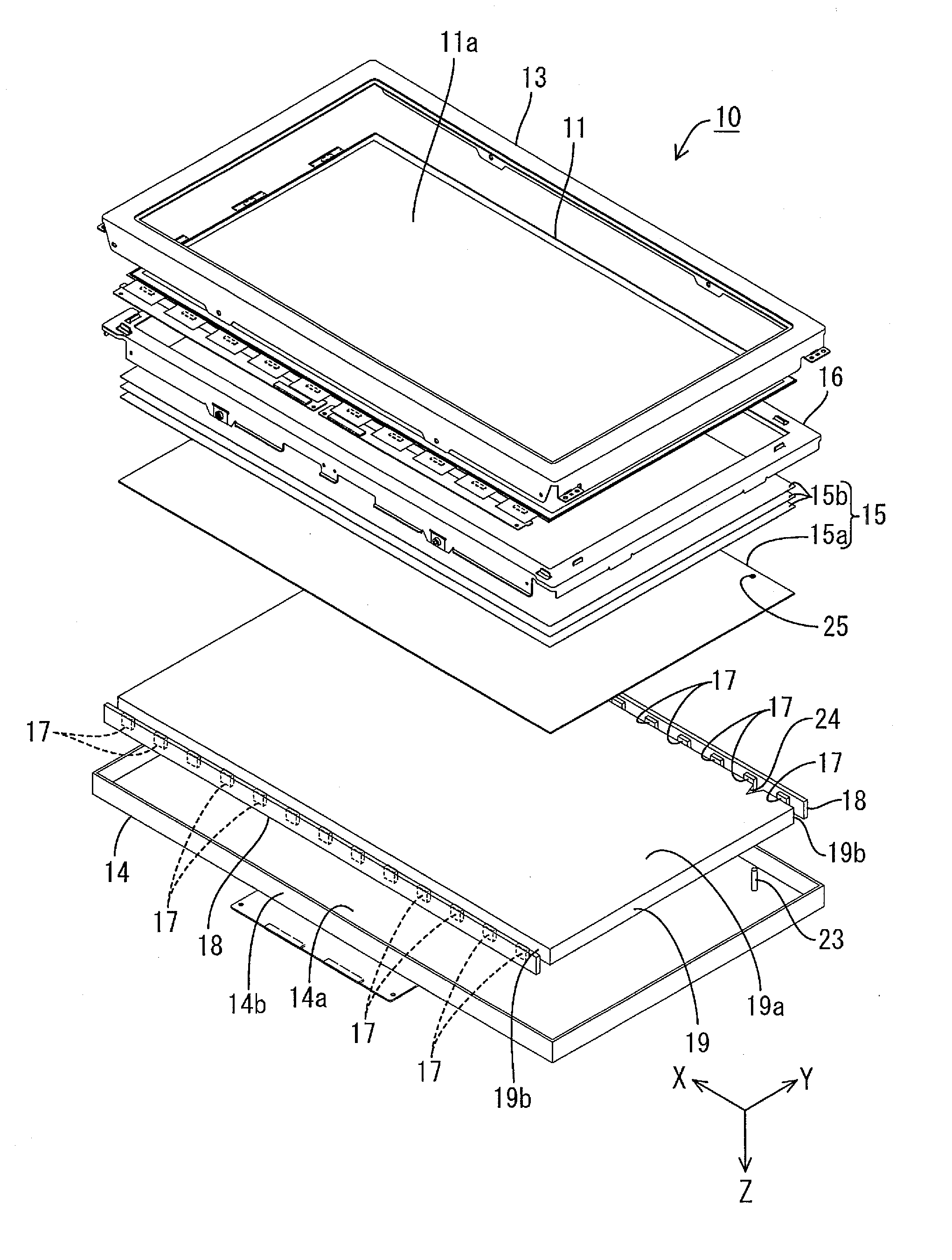
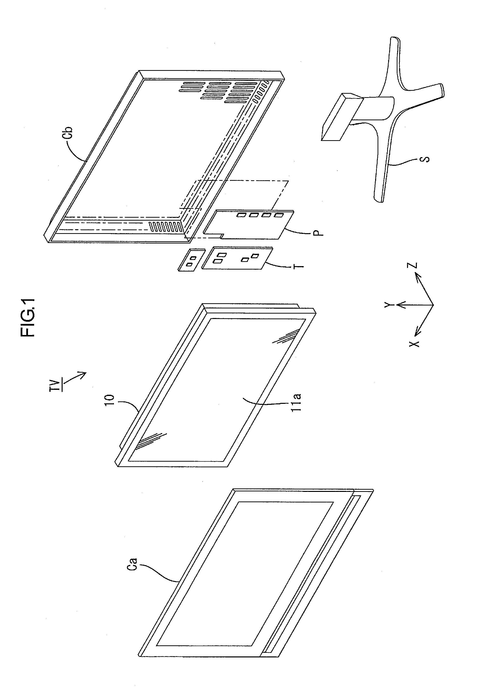
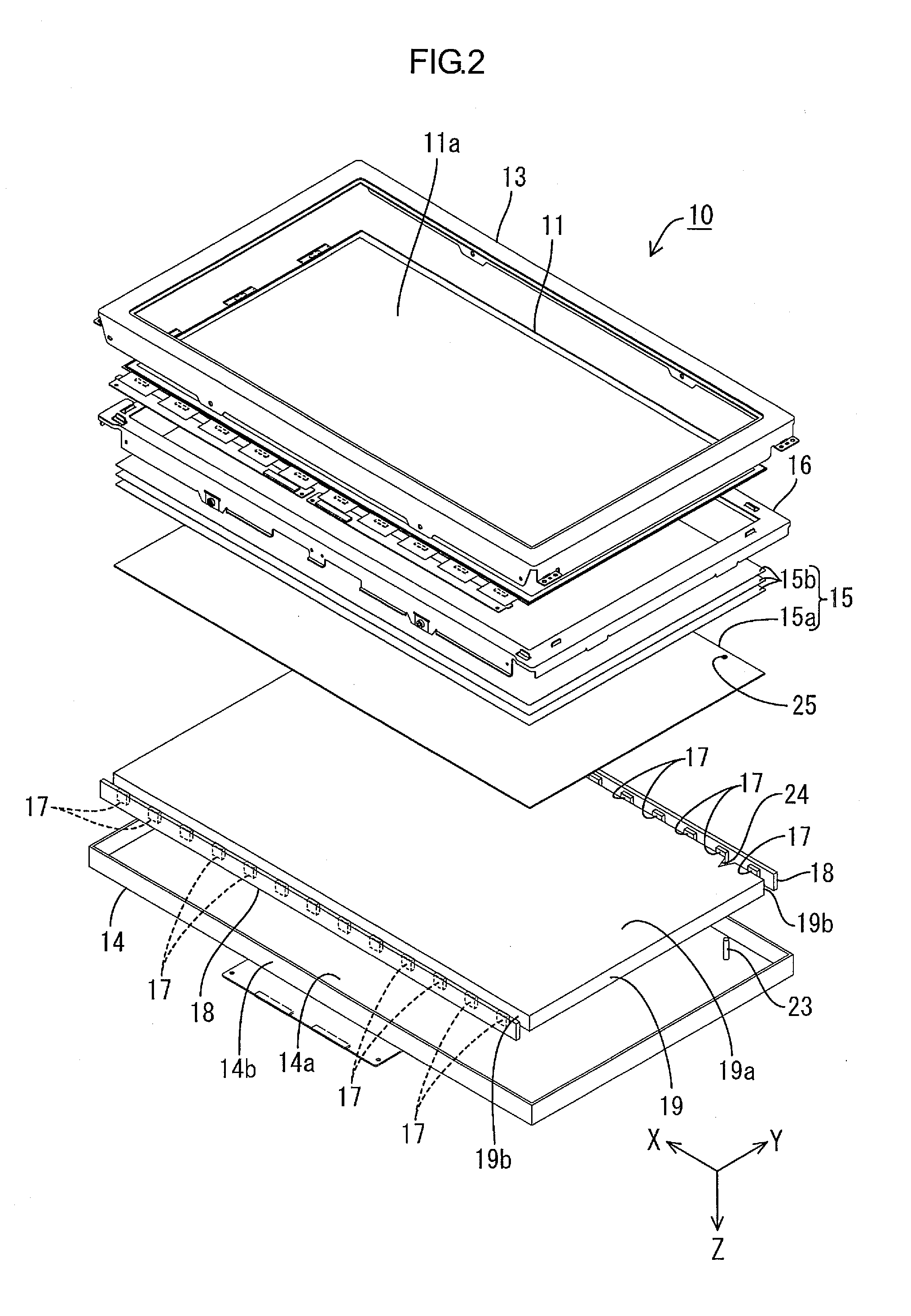
[0056]A first embodiment of the present invention will be described with reference to FIGS. 1 to 8. In this embodiment, a liquid crystal display device 10 will be explained. An X-axis, a Y-axis and a Z-axis are described in a part of the drawings, and a direction of each axial direction corresponds to a direction described in each drawing. The Y-axis direction and the X-axis direction, respectively, correspond to a vertical direction and a horizontal direction. The description of upper and lower side is based on the vertical direction unless otherwise specified. Additionally, the upper side in FIG. 2 corresponds to a front side, and the lower side therein corresponds to a rear side.
[0057]As illustrated in FIG. 1, a television receiver TV according to the present embodiment includes a liquid crystal display device 10, front and back cabinets Ca and Cb, a power supply P, a tuner T, and a stand S. The front and back cabinets Ca and Cb sandwich, and thus house, the liquid crystal displa...
first modification
of First Embodiment
[0110]The first modification of the first embodiment will be explained with reference to FIG. 9. The shape of a cutout 24-1 differs from that of the cutout 24.
[0111]As illustrated in FIG. 9, the cutout 24-1 of the first modification has a triangular shape in a plan view. The cutout 24-1 has side surfaces 24a-1 each of which substantially matches and extends parallel to a one-dotted line that indicates the outermost of the irradiation area LA of the LED 17. With this configuration, the light emitted from the LED 17 hardly enter the cutout 24-1.
second modification
of First Embodiment
[0112]The second modification of the first embodiment will be explained with reference to FIG. 10. The shape of a cutout 24-2 differs from that of the cutout 24.
[0113]As illustrated in FIG. 9, the cutout 24-2 of the second modification has a trapezoidal shape in a plan view. The cutout 24-2 includes a pair of side surfaces 24a-2 and a surface 24b. The side surfaces 24a-2 incline with respect to the Y-axis direction and the X-axis direction. The surface 24b connects ends of the side surfaces 24a-2 on the side opposite to the LED 17 side and extends parallel to the X-axis direction. With this configuration, the light emitted from the LED 17 hardly enter the cutout 24-2.
[0114]As described above, the cutout 24-2 of the present modification has a trapezoidal shape in a plan view. In such a configuration, the side surfaces 24a-2 (the interfaces) of the cutout 24-2 includes a portion inclined with respect to the arrangement direction of the LED 17 and the light guide mem...
PUM
| Property | Measurement | Unit |
|---|---|---|
| distance | aaaaa | aaaaa |
| dimension | aaaaa | aaaaa |
| thickness | aaaaa | aaaaa |
Abstract
Description
Claims
Application Information
 - R&D
- Intellectual Property
- Life Sciences
- Materials
- Tech Scout
- Unparalleled Data Quality
- Higher Quality Content
- 60% Fewer Hallucinations
Browse by: Latest US Patents, China's latest patents, Technical Efficacy Thesaurus, Application Domain, Technology Topic, Popular Technical Reports.
© 2025 PatSnap. All rights reserved.Legal|Privacy policy|Modern Slavery Act Transparency Statement|Sitemap|About US| Contact US: help@patsnap.com


