
Light source device and surface illuminating device using same light source device

A light source device and surface lighting technology, which is applied to lighting devices, components of lighting devices, and damage prevention measures of lighting devices, etc., can solve the problems of narrow lighting area and damage to eyes, etc.

Inactive Publication Date: 2015-02-18
OPTO DESIGN INC
View PDF6 Cites 0 Cited by
  • Summary
  • Abstract
  • Description
  • Claims
  • Application Information

AI Technical Summary

Problems solved by technology

Compared with incandescent light bulbs or fluorescent lamps, etc., LEDs have excellent characteristics such as power saving, long life, and small size. On the other hand, due to their strong directivity, the lighting area is extremely narrow, and there is a risk of damage to the eyes when looking directly at the light. and other disadvantages, so when used as illumination light, technology for efficiently diffusing the light is required

Method used


Image

  • Light source device and surface illuminating device using same light source device
  • Light source device and surface illuminating device using same light source device
  • Light source device and surface illuminating device using same light source device

Examples


Embodiment approach 1

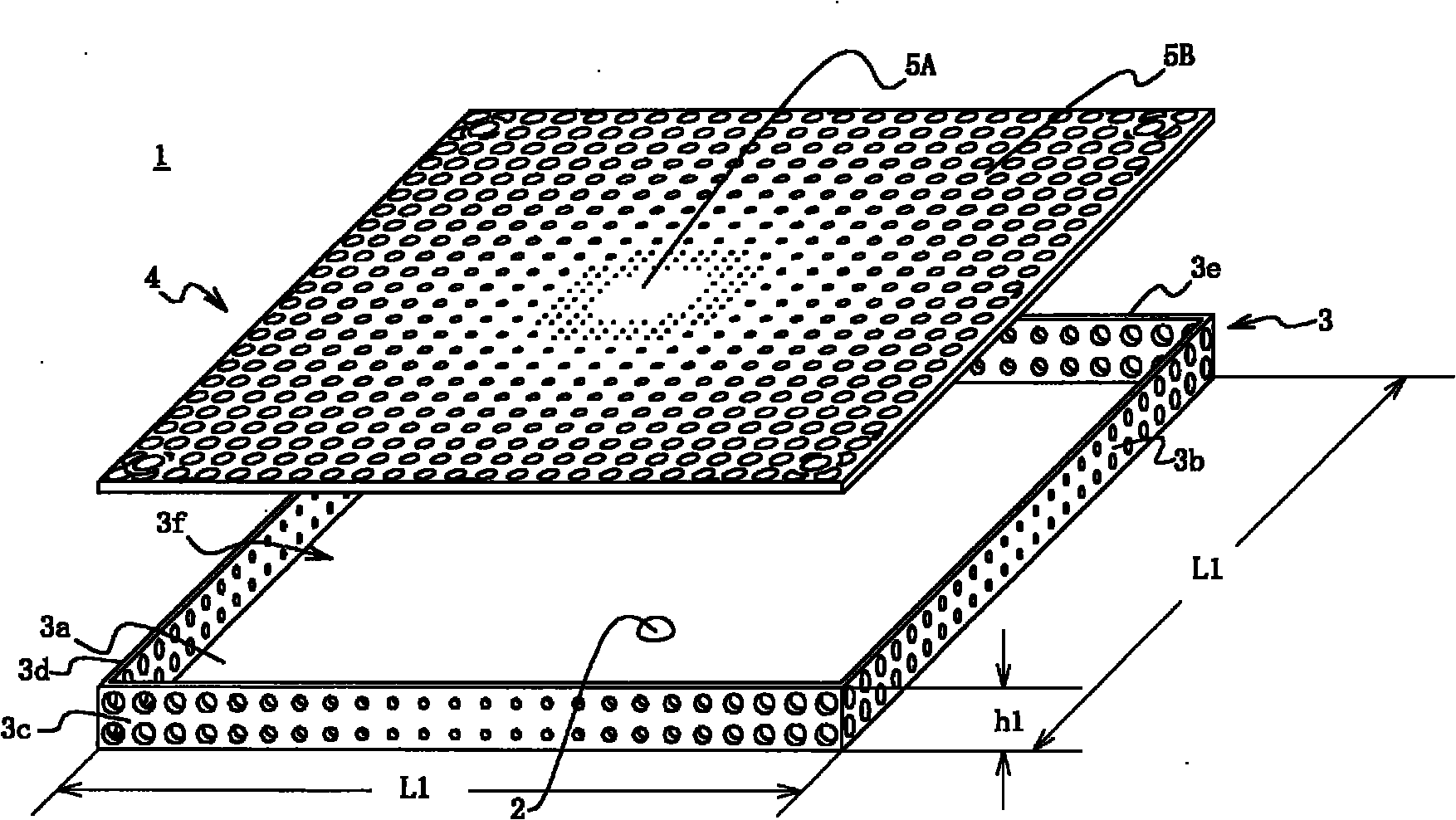
[0072] refer to figure 1 , the outline of the light source device according to Embodiment 1 of the present invention will be described. in addition, figure 1 It is an exploded perspective view of the light source device according to Embodiment 1 of the present invention.

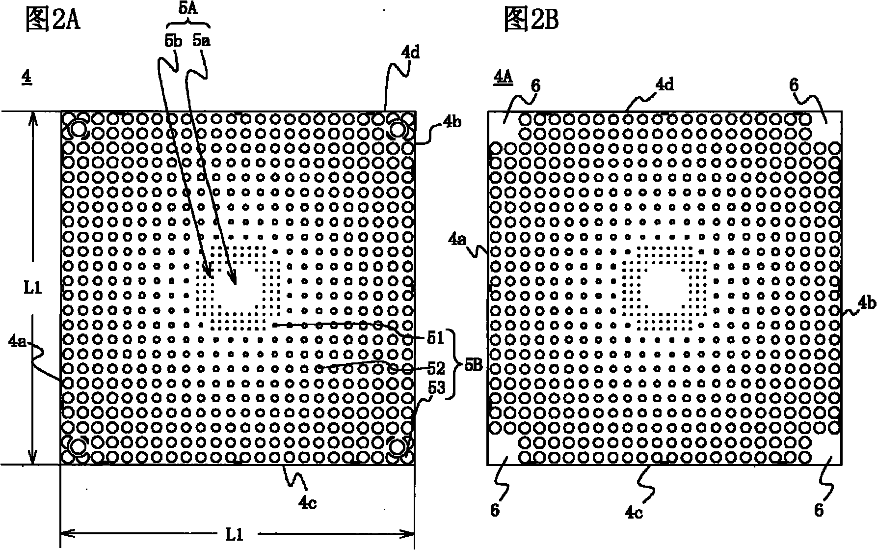
[0073] The light source device 1 is composed of a point light source 2 , a box-shaped casing 3 with the point light source installed on the bottom plate and an upper opening, and an optical reflector 4 covering the opening of the casing and reflecting and transmitting light from the point light source 2 .

[0074] As the point light source 2 , one LED or an LED in which a plurality of LED elements are assembled (hereinafter, these are collectively referred to as LEDs) or an LD is used. The LEDs may not only be LEDs of the three primary colors R, G, and B, but may also be LEDs of other colors. In addition, a lens may be attached to the LED or LD. In this embodiment, an example using LEDs will be described....

Embodiment approach 2

[0090] Next, refer to Figure 4 , the surface lighting device according to Embodiment 2 of the present invention will be described. in addition, Figure 4 It is a schematic plan view of the surface lighting device according to Embodiment 2 of the present invention, Figure 5 It is cut along the V-V line Figure 4 Cross-sectional view of the surface lighting device. In addition, in Figure 4 In , the diffuser plate of the bottom illuminator can be removed to observe the interior.

[0091] Such as Figure 4 and Figure 5 As shown, the surface lighting device 8 is configured to have four light source devices 1, a storage case 9 for storing these light source devices, and a diffusion plate 10 for closing the opening of the storage case and diffusing the emitted light from each light source device. Four light source devices 1 are arranged in the case 9 with predetermined gaps (distances) therebetween, and the opening of the housing case 9 is covered with a diffuser plate 10 ...

Embodiment approach 3

[0108] refer to Figure 9 , Figure 10 , the surface lighting device according to Embodiment 3 of the present invention will be described. in addition, Figure 9 A light source device and a surface lighting device using the light source device according to Embodiment 3 of the present invention are shown, Figure 9 A is a schematic top view, Figure 9 B is Figure 9 A side view of the face illuminator of A, Figure 9 C is Figure 9 Sectional view of line IXC-IXC of A, Figure 10 show Figure 9 A modified example of the surface lighting device of A, Figure 10 A is a top view, Figure 10 B is Figure 10 A cross-sectional view of line XB-XB. In addition, in Figure 9 A. Figure 10 In A, the inside can be observed by removing the diffuser plate of the bottom illuminator.

[0109] Part of the configuration of the light source devices 1 and 1A described above and the surface lighting devices 8 , 8B, and 8C using these light source devices may be changed depending on th...


PUM


Abstract

A light source device of the present invention includes: a point light source 2 having high directionality; a housing 3 that has a housing bottom plate arranged with the point light source 2, housing side plates arranged in a standing manner from a periphery of the housing bottom plate to a predetermined height, and a side defining an opening provided facing the housing bottom plate, and that is formed on inner wall surfaces thereof with reflective surfaces; and an optical reflective plate 4 that covers the opening and emits light from the point light source as substantially uniform illumination light. Each of at least some of the housing side plates is provided with a side central reflective portion having a high optical reflectance and a low optical transmittance in a side plate region nearest to the point light source 2, and provided, in outer side plate regions of the side central reflective portion, with side outer reflective portions that have an optical reflectance decreasing and an optical transmittance increasing as being distant from the side central reflective portion. With the present invention, it is possible to provide a light source device that can be used for multiple purposes by enabling to emit illumination light from multiple faces.

Description

technical field [0001] The present invention relates to a light source device and a surface lighting device using the light source device. lighting fixtures. Background technique [0002] In recent years, lighting devices using highly directional point light sources such as light emitting diodes (hereinafter referred to as LEDs) and laser diodes (hereinafter referred to as LDs) have been developed instead of conventional incandescent light bulbs or fluorescent lamps, and have begun to be used in display devices and the like. Compared with incandescent light bulbs or fluorescent lamps, etc., LEDs have excellent characteristics such as power saving, long life, and small size. On the other hand, due to their strong directivity, the lighting area is extremely narrow, and there is a risk of damage to the eyes when looking directly at the light. Therefore, when used as illumination light, a technique for efficiently diffusing the light is required. Therefore, in order to utilize...

Claims


Application Information

Patent Timeline
Patent Type & Authority Patents(China)
IPC IPC(8): F21S2/00F21V7/00F21V11/14F21Y101/02
CPCF21Y2101/025F21Y2105/001F21V15/01F21Y2105/00F21K9/00F21V11/14F21Y2101/02F21K9/68F21Y2105/10F21Y2115/10F21Y2115/30F21K9/20F21Y2101/00F21Y2105/16
Inventor 佐藤荣一佐藤弘泰佐藤研
Owner OPTO DESIGN INC
Learn More