Lighting device, display device and television device
a technology of display device and light source, which is applied in the direction of lighting and heating apparatus, television systems, instruments, etc., can solve the problems of less efficient use, less efficient use of front direction as outgoing light, and large angle of light emitted from the light sour
- Summary
- Abstract
- Description
- Claims
- Application Information
AI Technical Summary
Benefits of technology
Problems solved by technology
Method used
Image
Examples
first embodiment
[0074]The first embodiment of the present invention will be described with reference to FIG. 1 to FIG. 9. In the present embodiment, a liquid crystal display device 10 will be described. An X-axis, a Y-axis, and a Z-axis are described in a part of the drawings, and a direction of each axial direction corresponds to a direction described in each drawing. An upper side in FIG. 4 and FIG. 5 corresponds to a front-surface side and a lower side in FIG. 4 and FIG. 5 corresponds to a rear-surface side.
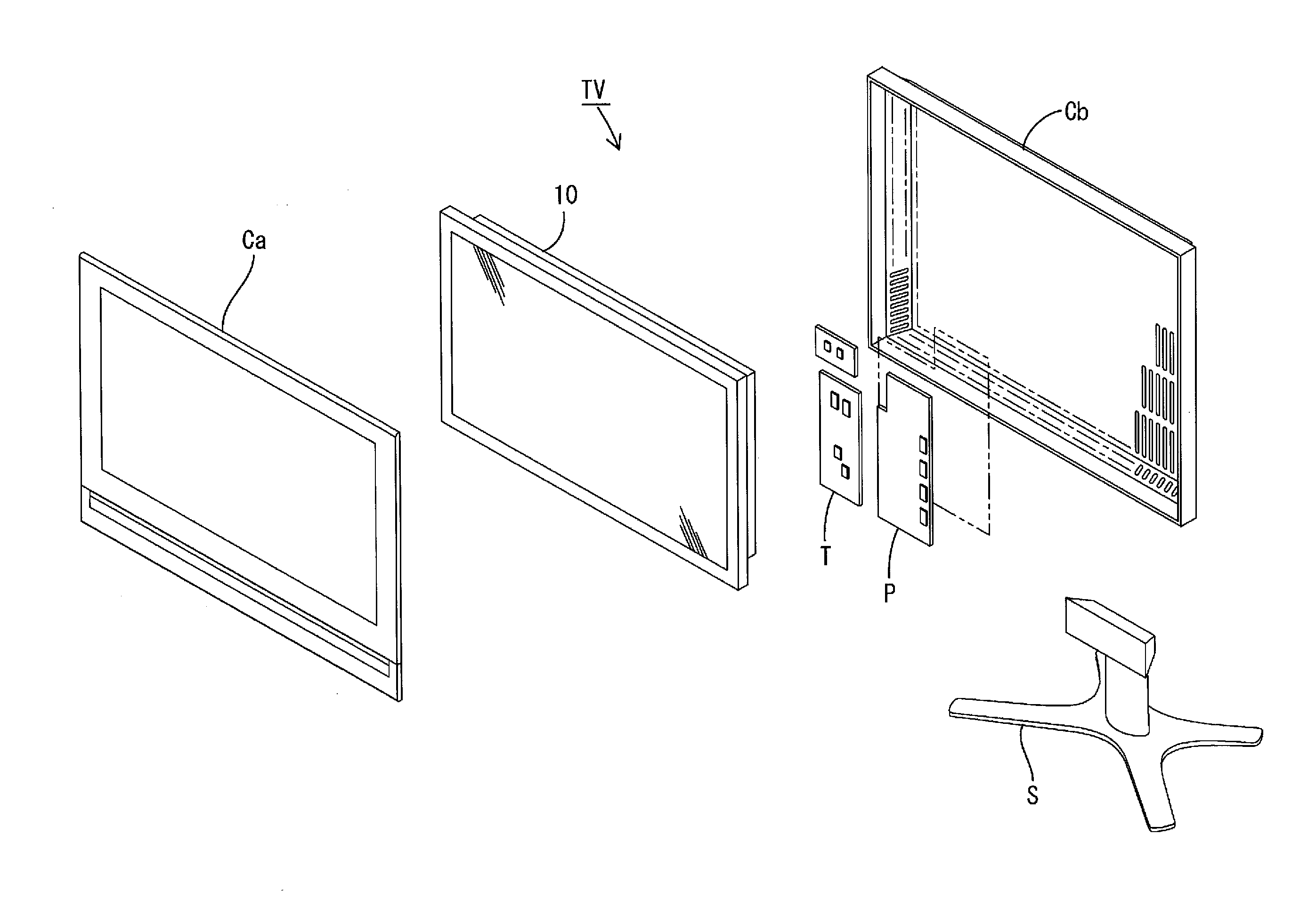
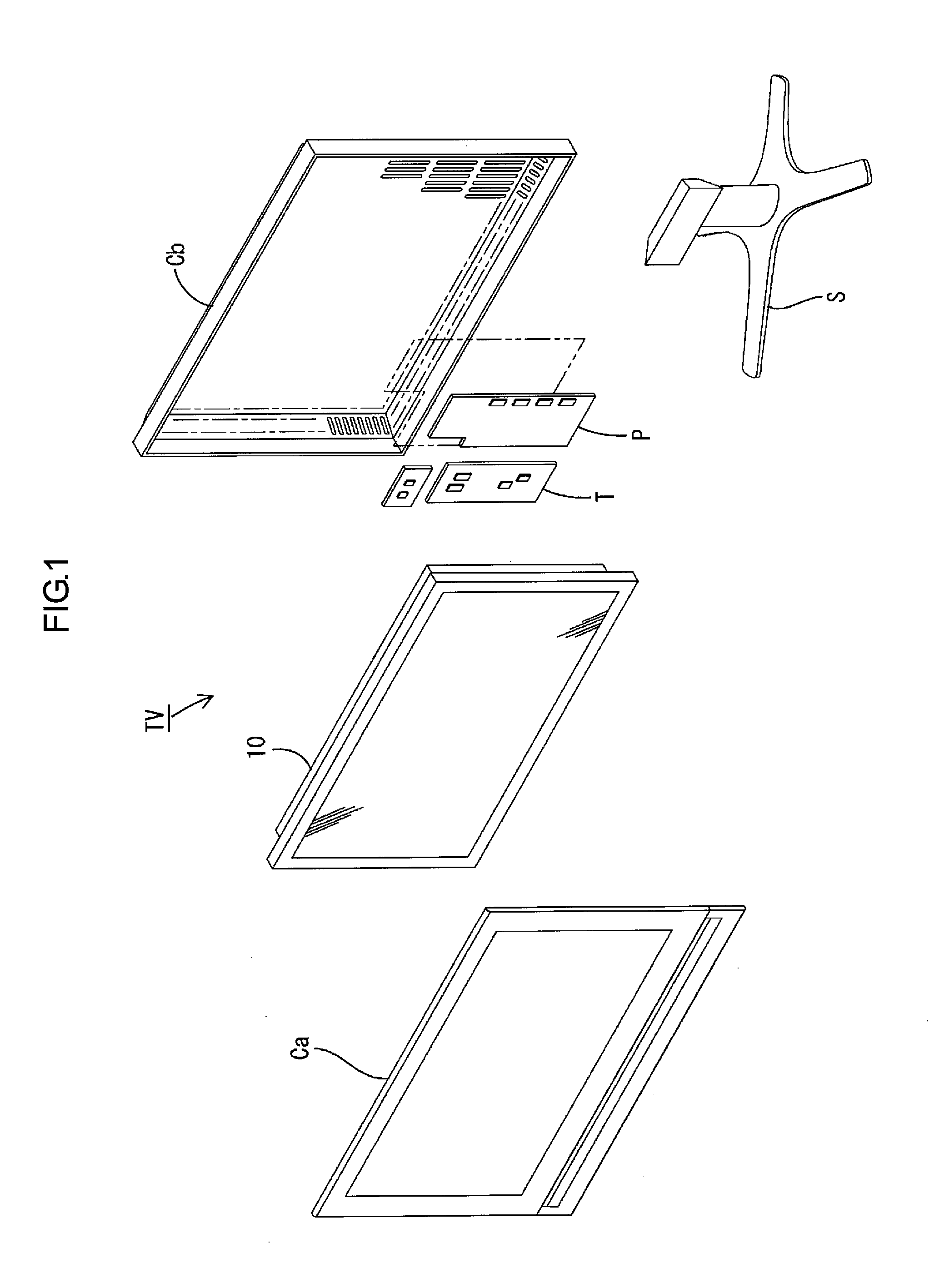
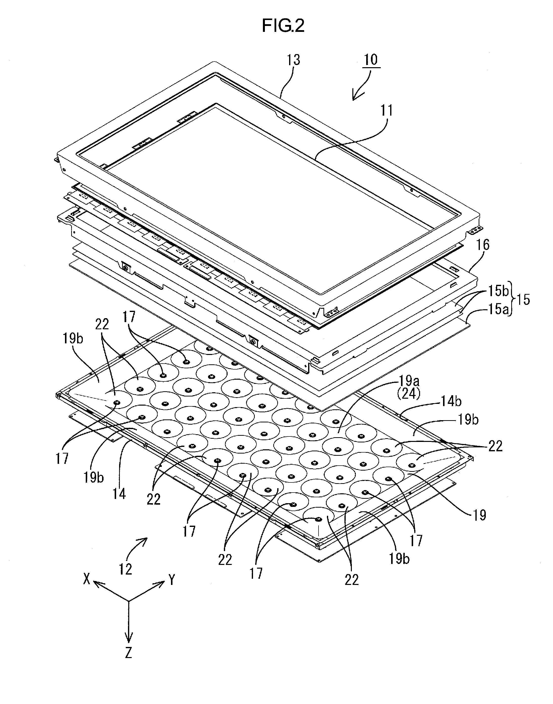
[0075]As illustrated in FIG. 1, the television device TV of the present embodiment includes the liquid crystal display device 10, front and rear cabinets Ca, Cb which house the liquid crystal display device 10 therebetween, a power source P, a tuner T, and a stand S. The entire shape of the liquid crystal display device (a display device) 10 is a landscape (elongated) rectangular (square) shape. The liquid crystal display device 10 is housed in a vertical position. As illustrated in FIG. 2, t...
fourth modification
of First Embodiment
[0136]The fourth modification of the first embodiment will be explained with reference to FIG. 15. The cross section of a light leading member 22-4 taken along the Z-axis direction is changed.
[0137]As illustrated in FIG. 15, the light leading member 22-4 of the present modification has an arc-like cross-section taken along the Z-axis direction (the front direction), and the light leading surface 22a-4 thereof is a substantially curved surface. Specifically, the light leading member 22-4 is curved to the LED board 18 side, i.e., in a direction opposite to the light exit side, and thus has a bowl shape as a whole. The light leading member 22-4 has an arc-like cross-section taken along the Z-axis direction, and the light leading surface 22a-4 thereof is a substantially curved surface. The light leading member 22-4 having such a configuration can sufficiently lead the light emitted from each LED 17 toward the front side by the light leading surface 22a-4 having the ar...
fifth modification
of First Embodiment
[0139]The fifth modification of the first embodiment will be explained with reference to FIG. 16. The cross section of a light leading member 22-5 is further changed from the above fourth modification.
[0140]As illustrated in FIG. 16, the light leading member 22-5 of the present modification protrudes toward the optical member 15, i.e., the light exit side, such that the distance between the light leading member 22-5 and the optical member 15 gradually decreases. Namely, the light leading member 22-5 has the arc-like cross-section taken along the Z-axis direction (the front direction), and thus the light leading surface 22a-5 is a curved surface curved closer to the optical member 15. The light leading member 22-5 having such a configuration can sufficiently lead the light emitted from each LED 17 toward the front side by the light leading surface 22a-5 having the arc-like shape. The angle θ2 (-θ2) between the light leading member 22-5 (the light leading surface 22...
PUM
| Property | Measurement | Unit |
|---|---|---|
| angle | aaaaa | aaaaa |
| angle | aaaaa | aaaaa |
| angle | aaaaa | aaaaa |
Abstract
Description
Claims
Application Information
 - R&D
- Intellectual Property
- Life Sciences
- Materials
- Tech Scout
- Unparalleled Data Quality
- Higher Quality Content
- 60% Fewer Hallucinations
Browse by: Latest US Patents, China's latest patents, Technical Efficacy Thesaurus, Application Domain, Technology Topic, Popular Technical Reports.
© 2025 PatSnap. All rights reserved.Legal|Privacy policy|Modern Slavery Act Transparency Statement|Sitemap|About US| Contact US: help@patsnap.com


