
A kind of anode tank, raw foil machine, electrolyte flow production method of electrolytic copper foil

A technology of anode tank and foil machine, applied in electrolysis components, electrolysis process, electroforming, etc., can solve problems such as uneven thickness of copper foil, excessive Reynolds number of liquid inlet, and no research, so as to reduce copper foil Inhomogeneity, guarantee of uniformity of copper foil thickness, and effect of ensuring deposition effect

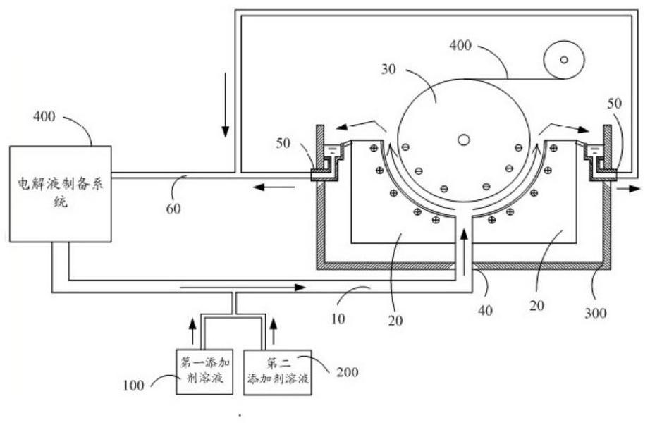
Active Publication Date: 2020-12-08
GUANGDONG FINE YUAN SCI TECH CO LTD
View PDF12 Cites 0 Cited by
  • Summary
  • Abstract
  • Description
  • Claims
  • Application Information

AI Technical Summary

Problems solved by technology

[0004] For the design of CN102277597A, it adopts the method of feeding liquid from the bottom, which has the following problems: 1) the liquid feeding from the bottom will drive oxygen, acid gas, etc. to the liquid surface, causing the risk of oxidation of copper foil; 2 ) The Reynolds number of the liquid inlet of the lower liquid inlet is too large, causing the thickness of the copper foil formed near the lower liquid inlet to be uneven from that of other parts
[0011] 1) It is easy to form turbulent flow at the liquid inlet and outlet (the liquid inlet needs a large flow rate, otherwise the old liquid cannot be pushed to the liquid return port), resulting in the thickness of the copper foil corresponding to the liquid inlet and outlet cannot be well controlled;
[0012] 2) The distribution field of copper ions: it must be that the liquid inlet is large and the liquid return port is small. The difference in the distribution field of copper ions will also lead to uneven thickness of the copper foil deposited by the cathode roller
[0013] And how to solve the above two problems, there is still no research in the prior art

Method used


Image

  • A kind of anode tank, raw foil machine, electrolyte flow production method of electrolytic copper foil
  • A kind of anode tank, raw foil machine, electrolyte flow production method of electrolytic copper foil
  • A kind of anode tank, raw foil machine, electrolyte flow production method of electrolytic copper foil

Examples


Embodiment 1

[0100] Example 1, such as Figure 5-7 Shown:

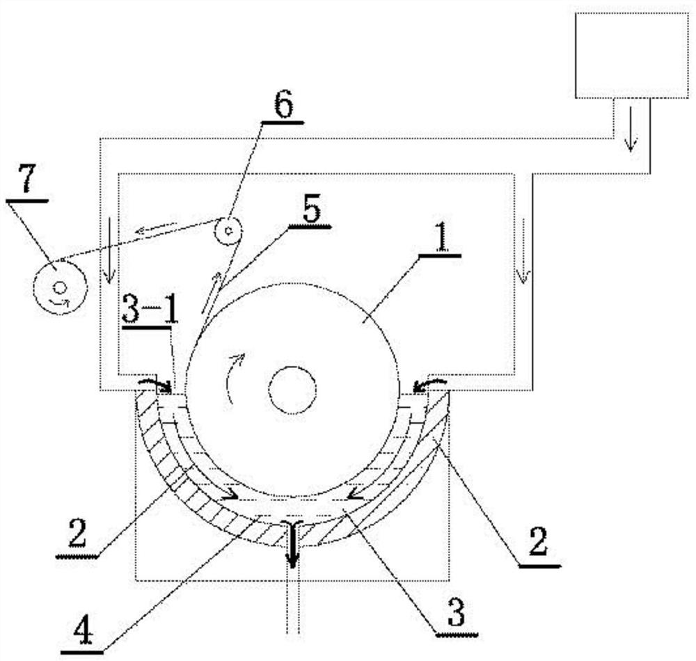
[0101] A foil production machine, comprising: an anode tank, a cathode roller 2, and an electrolyte adding pipeline 3;

[0102] The anode tank has a hollow structure, and the anode tank includes: an anode plate 1-1 on the side of the cathode roller, a fixing plate 1-2 on the side away from the cathode roller, and a lateral fixing plate;

[0103] The anode plate 1-1 is composed of a plurality of anode veneers 1-1-1, and the plurality of anode veneers form an arc-shaped anode plate;

[0104] Wherein, two adjacent anode veneers are provided with corresponding recesses 1-1-2 on their respective adjacent edges;

[0105] The recess of the anode veneer and the corresponding recess of the adjacent anode veneer form an opening;

[0106] The electrolyte pipeline 3 includes: a main pipeline and a plurality of branch pipelines, the main pipeline is connected with the branch pipelines, the main pipeline of the electrolyte pipeline 3 penetra...

Embodiment 1

[0109] The advantage of Embodiment 1 is: the branch pipeline protrudes from the surface of the anode plate of the anode tank, and several branch pipes are evenly distributed on the entire surface of the anode tank, and the liquid inlet of the electrolyte is a branch pipe; it makes the copper ions flow along the cathode The concentration in the direction of rotation of the roller remains basically unchanged (the supplement of copper ions does not need to go through a long path, but directly reaches the vicinity of the cathode roller), which ensures the deposition effect of the copper foil and reduces the occurrence of uneven copper foil (this application It is not through additives to improve the unevenness of copper foil).

Embodiment 2

[0110] Embodiment 2: as Figure 5 The design (embodiment 1) is also the upper liquid return port, and the upper liquid return port will face the problem of rising acid gas.

[0111] To this end, the improvements are as follows:

[0112] Such as Figure 8 Shown: Non-immersed anode cell:

[0113] A sealing roller 4 (height lower than the height of the peeling roller) is arranged at the upper port of the foil outlet side of the anode tank;

[0114] It also includes: an upper plate 5-1, a lower plate 5-2, and two side plates; the sealing roller 4 is arranged above the anode tank and is in contact with the cathode roller 2, and the length of the sealing roller 4 is the same as that of the cathode The length of the roller 2 is adapted; the sealing roller 4 is hinged on the upper plate 5-1;

[0115] The lower plate 5-2 is arranged outside the upper port of the anode tank;

[0116] The upper plate 5-1, the lower plate 5-2, and two side plates form an electrolyte pipeline (for ref...


PUM


Abstract

The invention discloses an anode tank, a crude foil engine and a method for producing electrolytic copper foil through electrolyte flowing, and belongs to the technical field of electrolytic copper foil production equipment. The crude foil engine is technically characterized by comprising the anode tank and an electrolyte pipeline (3), wherein the anode tank comprises an anode plate located on oneside of a cathode roller, and a plurality of electrolyte inlet holes are formed in the surface of the anode plate; the electrolyte pipeline (3) comprises a main pipeline and a plurality of branch pipelines, the main pipeline is connected with the branch pipelines, the main pipeline of the electrolyte pipeline (3) penetrates into the anode tank (1), and the branch pipelines penetrate through the electrolyte inlet holes and point to the cathode roller; and a scattering pipe is further arranged on the crude foil engine. The invention aims to provide the anode tank, the crude foil engine and themethod for producing the electrolytic copper foil through electrolyte flowing, and the uniformity of indexes such as surface density and thickness of the electrolytic copper foil is improved.

Description

technical field [0001] The invention relates to the field of electrolytic copper foil, and more specifically relates to a method for producing electrolytic copper foil by flowing an anode tank, a foil machine, and an electrolyte. Background technique [0002] Areal density and copper foil thickness uniformity are key indicators of electrolytic copper foil. How to increase the areal density of electrolytic copper foil and how to improve the thickness uniformity of copper foil have always been the key research topics of major companies. [0003] as attached figure 1 Shown, CN102277597A discloses the preparation of a kind of special lithium battery double-sided photoelectrolytic copper foil, and it comprises the following steps: get the first additive solution, the second additive solution and copper sulfate electrolytic solution; Copper ion content in the copper sulfate electrolytic solution 70~100g / L, sulfuric acid content 100~170g / L, chloride ion content 0.01~0.04g / L, coppe...

Claims


Application Information

Patent Timeline
Patent Type & Authority Patents(China)
IPC IPC(8): C25D1/04C25D3/38C25D7/06C25D17/00
CPCC25D1/04C25D3/38C25D7/0685C25D17/00
Inventor 张佳梓郭丽平刘少华邹子萍张小玲林远钦
Owner GUANGDONG FINE YUAN SCI TECH CO LTD
Learn More