
Heat bonding method and heat bonding device

a heat bonding and zipper technology, applied in the field of heat bonding methods and heat bonding devices, can solve the problems that the methods described in patent documents 1 to 3 cannot be applied to this kind of circumstance, zipper tapes cannot be effectively heat-bonded to the film without generating wrinkles, and wrinkles on the main body film, etc., to achieve easy heat-bonding to each other, no wrinkles, and easy engagement with each other

Inactive Publication Date: 2012-12-13
CHOKOKU PLAST CORP
View PDF0 Cites 5 Cited by
  • Summary
  • Abstract
  • Description
  • Claims
  • Application Information

AI Technical Summary

Benefits of technology

[0028]According to Aspect (1), because the engaging elements of the zipper tape are positioned within the first groove, the zipper tape can be kept straight without being twisted.
[0029]Consequently, the zipper tape can be heat-bonded in a linear fashion in a direction in which the first groove extends. Because the guide unit is provided with the cooling means for cooling the vicinity of the first groove, the inside of the first groove can be kept cold. Therefore, even when the zipper tape and the film are heat-bonded to each other by the heating unit, the temperature of the engaging element part is prevented from increasing, preventing the engaging element part from being softened by heat. Furthermore, because the guide unit is provided with the cooling means for cooling the vicinity of the first groove, heat-bonding together the zipper tape and the film by means of the heating unit allows the surface of the film contacting with the guide unit to immediately release the heat to the guide part, thereby preventing the temperature of the film from increasing above the predetermined temperature. Thus, the surface of the film that is in contact with the guide unit is not melted by heat and therefore does not stick to the guide unit. Because the film is prevented from sticking to the guide unit in this manner, no wrinkles are generated on the film even when the film and the zipper tapes are sent sequentially. In addition, the method for heat-bonding together the zipper tape and the film while sequentially sending the film and the zipper tape can be easily passed on to the step of sequentially sending films and producing a bag.
[0030]According to Aspect (2), in addition to the effects of Aspect (1), the guide unit is provided with a second groove extending parallel to the first groove. Therefore, the engaging elements of the zipper tapes can be positioned within the first and second grooves. As a result, the zipper tapes can be kept straight without being twisted when conveyed. Moreover, the engaging elements can be kept parallel and close to each other. Thus, when continuously forming films into bags, the engaging elements can be engaged with each other easily without requiring alignment of the positions thereof.
[0031]According to Aspect (3), in addition to the effects of Aspect (1) or (2), the zipper tape and the film can be heat-bonded to each other easily, when the engaging elements of the zipper tape have a continuous structure in the longitudinal direction of the zipper tape.
[0032]According to Aspect (4), in addition to the effects of Aspect (1) or (2), the zipper tape and the film can be heat-bonded to each other easily, when the engaging elements of the zipper tape are provided discontinuously in the longitudinal direction of the zipper tape and the discontinuous engaging elements are provided in a plurality of rows in the width direction of the zipper tape.
[0033]According to Aspect (5), in addition to the effects of Aspect (2), the zipper tape and the film can be heat-bonded to each other easily, when the zipper tape is configured such that the engaging elements of one zipper tape are provided discontinuously in a longitudinal direction of the tape and a plurality of rows of the discontinuous engaging elements are provided in a width direction, while the engaging elements of the other zipper tape are provided as a continuous row in a longitudinal direction of the tape.

Problems solved by technology

However, when the flanges of the zipper tapes, including the tip parts thereof, are heat-bonded to the main body films by using the methods disclosed in Patent Documents 1 to 3, the main body films are fused to the seal receiver described in Patent Document 1 and to the drum described in Patent Document 2 or 3, causing wrinkles on the main body films.
Because such zipper tapes have no flanges, the zipper tapes cannot be effectively heat-bonded to the film without generating wrinkles.
Unfortunately, the methods described in Patent Documents 1 to 3 cannot be applied to this kind of circumstance.
The method described in Patent Document 2 or 3, on the other hand, heat-bonds the film and the zipper tapes to each other by the continuous operation of the rotating drum, which cannot easily be linked to the bag production step that carries out the intermittent operation.

Method used


Image

  • Heat bonding method and heat bonding device
  • Heat bonding method and heat bonding device
  • Heat bonding method and heat bonding device

Examples


embodiment 1

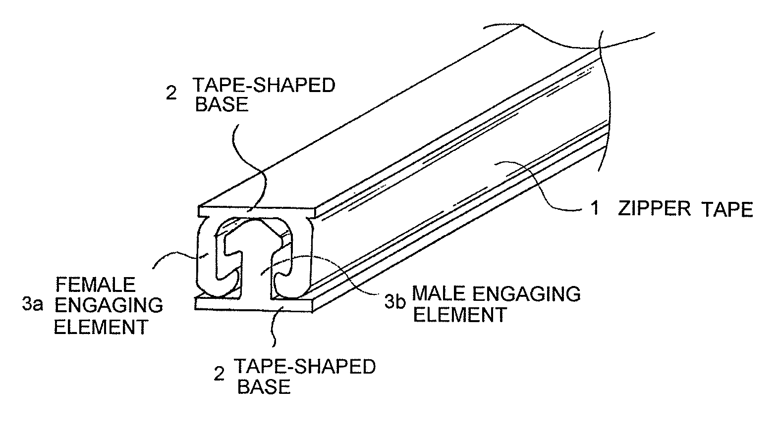
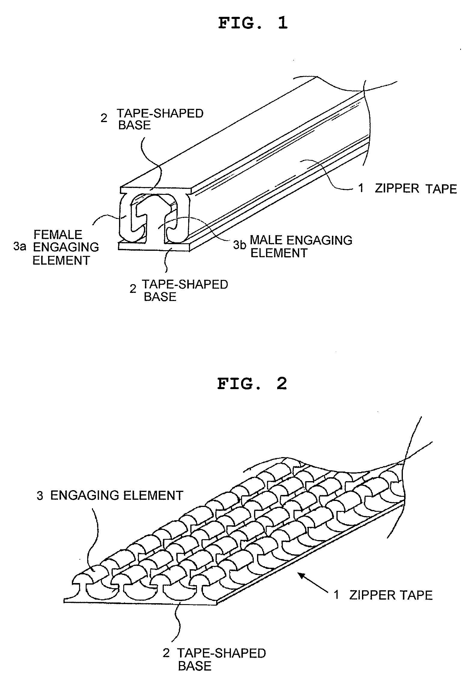
[0074]The present embodiment describes how the zipper tape shown in FIG. 1 is heat-bonded to the film.

[0075]FIG. 6 is a diagram showing the details of the heat bonding part H of the heat bonding device shown in FIG. 5, FIG. 6 showing an end view of a surface that is perpendicular to a direction in which the zipper tape shown in FIG. 1 and the film flow and also an end view of a state in which the heating units are separated.

[0076]FIG. 7 is an end view showing a state in which the heating units shown in FIG. 6 are in pressure-contact with the guide unit.

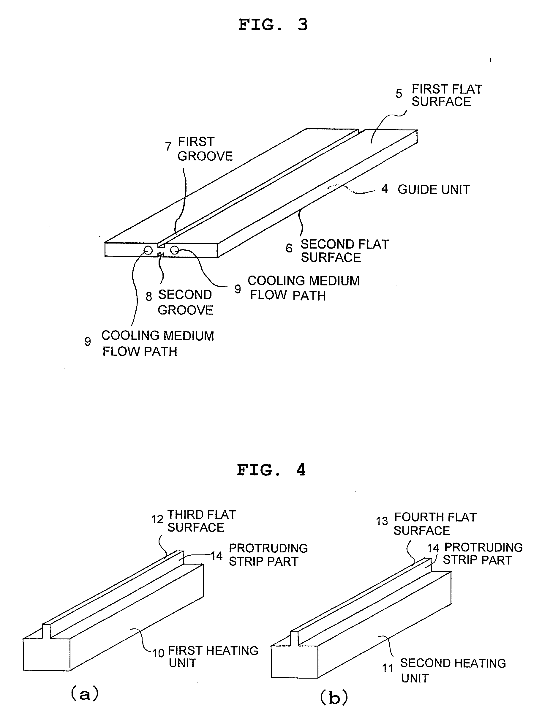
[0077]A plate-shaped rectangular guide unit made of aluminum or other metal is used as a guide unit as shown in FIG. 3.

[0078]A first flat surface 5 of this plate-shaped guide unit 4 is provided with a first groove 7 that extends linearly in a longitudinal direction of the guide unit 4. This first groove 7 is slightly wider than the width of the female engaging element 3a, as deep as the height of the element part of the female engagin...

embodiment 2

[0100]FIG. 2 is a diagram showing an example of the zipper tape used in the present embodiment.

[0101]In this zipper tape, a plurality of unit engaging elements are provided discontinuously in the longitudinal direction of the tape-shaped base and the discontinuously formed engaging elements are arranged in a plurality of parallel rows. This zipper tape can be engaged with another zipper tape by engaging a liner of engaging elements between opposing engaging elements, as viewed cross-sectionally in a width direction of the zipper tapes. In other words, rows of engaging elements of one zipper tape are shifted in the width direction so as to be positioned between rows of engaging elements of another zipper tape, and these engaging elements of the both zipper tapes are pressed against each other to push the engaging elements of the former zipper tape into the engaging elements of the latter zipper tape.

[0102]FIG. 8 shows an example in which the present embodiment is applied to the heat ...

example 1

[0110]An example of Embodiment 2 is described next. In the zipper tape shown in FIG. 2, the width of four rows of engaging elements was set at 5.2 mm, the height of the zipper tape at 1.2 mm, and the thickness and width of the tape-shaped base at 0.1 mm and 5.5 mm respectively. The material of the zipper tape was polypropylene.

[0111]The thickness of the guide unit was 5 mm. The width and depth of each of the first and second grooves were 5.4 mm and 1.2 mm, respectively. Water that was kept at 15° C. was used as the cooling medium.

[0112]The film was obtained by laminating together a biaxially-oriented polyethylene terephthalate film having a thickness of 12 mm and a cast polypropylene film having a thickness of 60 μm. The heat-bondable surface is a cast polypropylene film having a thickness of 60 μm.

[0113]The first and second heating units were kept at 160° C., and the widths of the third and fourth flat surfaces were set at 6 mm so as to cover approximately half of each of the first...


PUM

PropertyMeasurementUnit
Temperatureaaaaaaaaaa
Widthaaaaaaaaaa
Contentaaaaaaaaaa

Abstract

A method for heat-bonding together a film and a zipper tape using a heat bonding device including a guide unit which has at a first flat surface a linearly extending first groove for guiding an engaging elements of a zipper tape, the groove being slightly wider than a width of the engaging elements and slightly shallower than a height of the zipper tape, and which has cooling means for keeping a vicinity of the first groove cold, and a first heating unit that is disposed facing the first flat surface of the guide unit, has a third flat surface that is so shaped as to cover the first groove, and has a mechanism such that the third flat surface approaches and is separated from the position of the first flat surface.

Description

TECHNICAL FIELD[0001]The present invention relates to a method and device for producing a bag with a zipper, and more particularly to a method for attaching a zipper tape to a film configuring a bag main body and a producing device.TECHNICAL FIELD[0002]In a conventional method for producing a bag with a zipper, a synthetic resin part of zipper tapes is fused and bonded by heat to the surface of a synthetic resin film that becomes a bag main body, thereby producing a bag main body film, the zipper tapes each having a male or female engaging element on one side of a tape-shaped base film made of synthetic resin.[0003]For example, Patent Document 1 discloses a method for heat-bonding zipper tapes to films for a bag main body. This method is described with reference to FIGS. 10 and 11. This method first sandwiches a seal receiver 5 between flange parts 4 forming part of tape-shaped bases of zipper tapes 1, 2 that are engaged with each other beforehand. Further, main body films 3 are sup...

Claims


Application Information

Patent Timeline
IPC IPC(8): B65D33/25B32B37/14B32B37/08B32B3/06B31B50/64
CPCB32B37/08B32B37/14Y10T428/24008B31B1/00B31B2219/9019B65D33/25B65D33/2541B31B50/00B31B70/8131B31B70/8132
Inventor MATSUO, TETSUYA
Owner CHOKOKU PLAST CORP
Learn More