
Control system for an internal combustion engine

a control system and internal combustion engine technology, applied in the direction of electrical control, process and machine control, instruments, etc., can solve the problem of not always being able to estimate the amount of fresh air blowing by with sufficient accuracy

Inactive Publication Date: 2012-12-13
NISSAN MOTOR CO LTD
View PDF4 Cites 40 Cited by
  • Summary
  • Abstract
  • Description
  • Claims
  • Application Information

AI Technical Summary

Benefits of technology

[0009]According to the present invention, the fresh air blowby into the exhaust passage may be, though indirectly, measured by an actual measurement of mass flow detecting means, and a fresh air blowby amount will be estimated without being influenced by the fuel injection amount and / or the after-burn of the exhaust mixture within the exhaust passage.

Problems solved by technology

Therefore, there remains a problem of not always being able to estimate the amount of fresh air blowby with sufficient accuracy.

Method used


Image

  • Control system for an internal combustion engine
  • Control system for an internal combustion engine
  • Control system for an internal combustion engine

Examples


Embodiment Construction

[0021]In the following, an explanation of an embodiment according to the present invention will be made with reference to accompanying drawings.

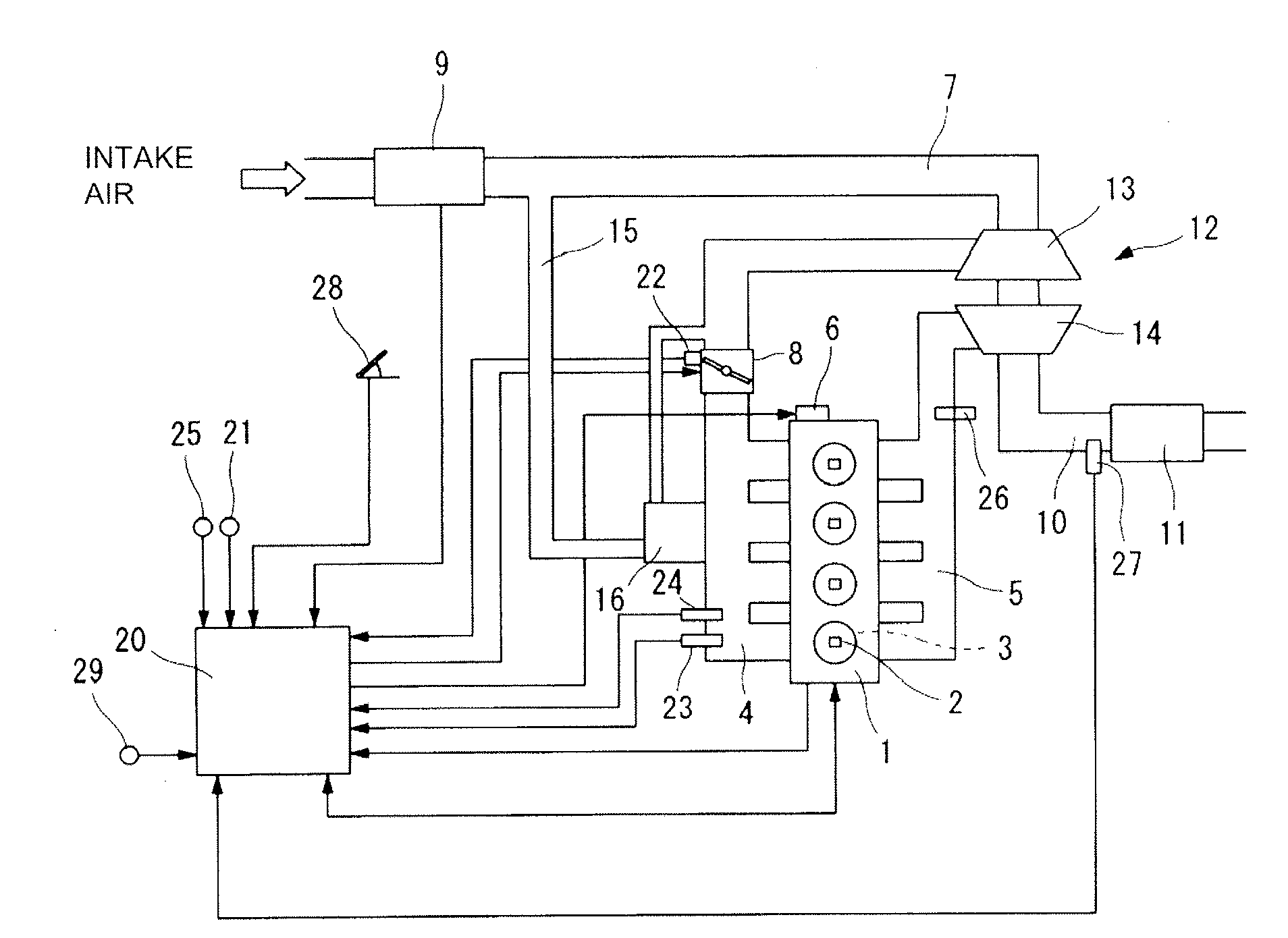
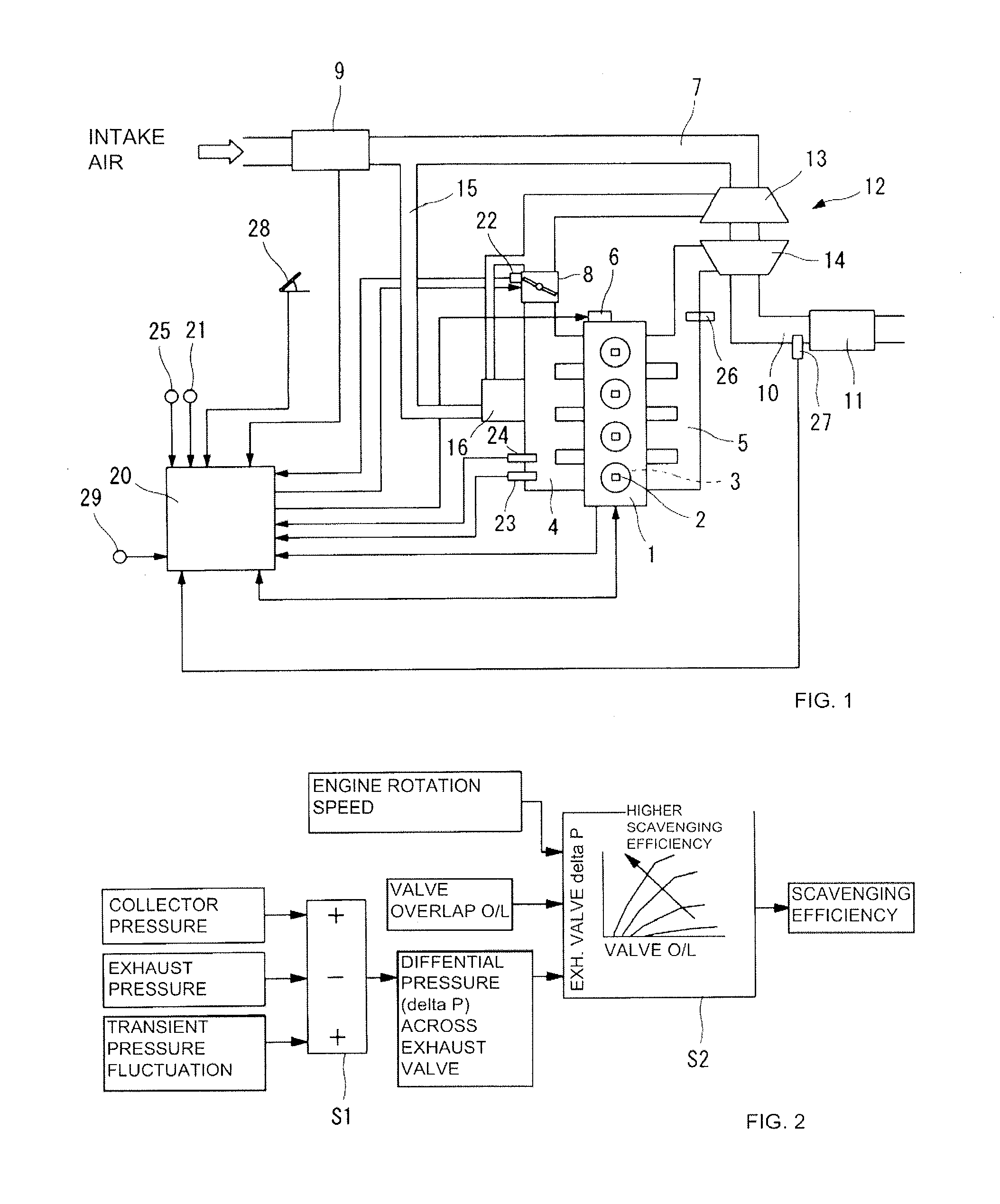
[0022]FIG. 1 is a overall view showing schematically an in-line four-cylinder, 4-stroke, internal combustion engine to which the present invention is applied. The internal combustion engine 1 is of an in-cylinder direct injection type in which fuel is directly injected into a combustion chamber defined by a cylinder 3. Each cylinder 3 is connected to an intake manifold 4 via intake valve and intake port (both not illustrated). Each cylinder 3 is further connected to an exhaust manifold 5 via exhaust valve and exhaust port (both not illustrated). Both the intake port and exhaust port are disposed in a cylinder head of each cylinder 3 so as to oppose to each other.

[0023]In the present embodiment, a variable valve mechanism 6 is employed as an intake valve driving mechanism and a valve lift characteristic of the intake valve is subject to be ch...


PUM


Abstract

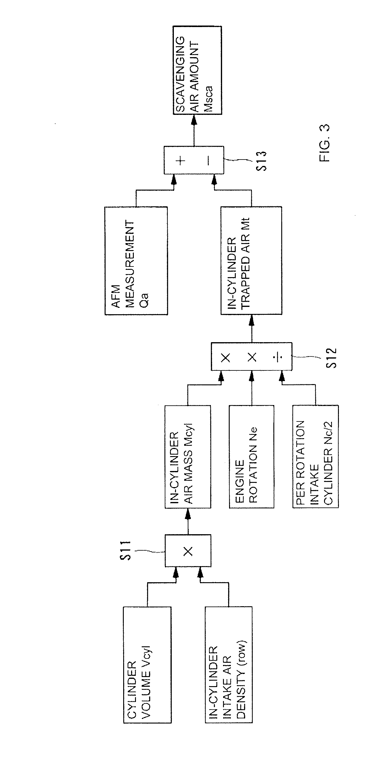
A control system for a direct-injection four-stroke internal combustion engine having at least one cylinder, an intake passage supplying air to the cylinder, and an exhaust passage removing exhaust gas from the cylinder, the control system including a mass air flow meter configured to detect a mass air flow upstream of the cylinder and a control unit. The control unit is configured to detect an intake air density in the cylinder, calculate an in-cylinder trapped intake air amount based on a cylinder volume and the detected intake air density, and estimate a difference between the intake air amount detected by the mass air flow meter and the in-cylinder trapped intake air amount, the estimated difference being an estimated scavenging amount representing a fresh air blowby amount passing from the intake passage into the exhaust passage.

Description

CROSS-REFERENCE TO RELATED APPLICATIONS[0001]This application claims priority under 35 U.S.C. §119 to Japanese Patent Application No. 2011-127238, filed on Jun. 7, 2011, which is incorporated by reference herein in its entirety.BACKGROUND OF THE INVENTION[0002]1. Field of Invention[0003]The present invention generally relates to a control system for an internal combustion engine in which a fresh air blowby amount passing from an intake passage through to an exhaust passage may be estimated based on a measurement of an intake air amount in the intake passage.[0004]2. Description of Related Art[0005]A conventional technology for reducing a residual gas amount within in a cylinder is to make effective use of a scavenging effect due to valve overlap, in which an amount of valve overlap is controlled according to an estimated amount of fresh air blowby which passes from an intake passage into an exhaust passage. The fresh air blow-by is estimated based on an oxygen concentration detected...

Claims


Application Information

Patent Timeline
Patent Type & Authority Applications(United States)
IPC IPC(8): F02D41/26F02D41/30
CPCF02D35/023F02D41/1445F02D41/18F02D41/22Y02T10/144F02D41/0007Y02T10/18Y02T10/40F02D13/0261Y02T10/12
Inventor TSUYUKI, TAKESHI
Owner NISSAN MOTOR CO LTD
Learn More