
Method of repairing a turbine nozzle segment in a turbine engine

a technology of turbine engines and nozzle segments, which is applied in the direction of machines/engines, stators, mechanical equipment, etc., can solve the problem of often more difficult repair

Active Publication Date: 2012-12-20
GENERAL ELECTRIC CO
View PDF7 Cites 6 Cited by
  • Summary
  • Abstract
  • Description
  • Claims
  • Application Information

AI Technical Summary

Benefits of technology

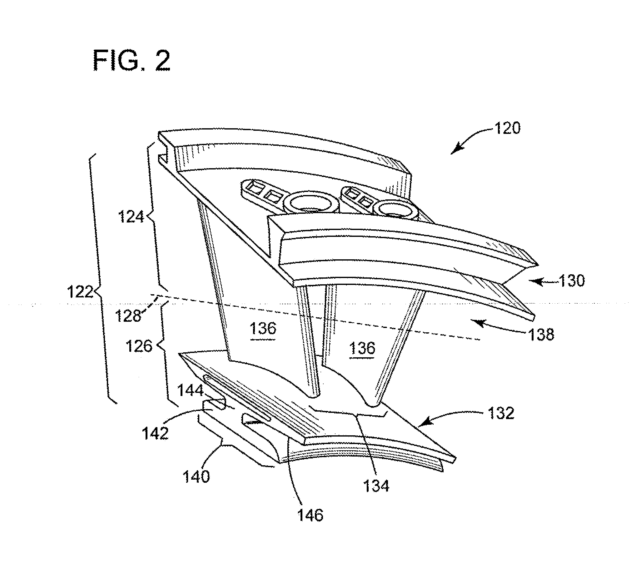
[0010]The methods described below can apply to turbine nozzles with configurations important to the operation of the turbine nozzle and the turbine engine as a whole. These configurations may integrate, for example, certain cooling features into the overall construction of the turbine nozzle. Because these cooling features rely, at least in part, on the entire construction of the turbine nozzle, repair is often more difficult. On the other hand, implementation of embodiments of the methods described herein can maintain the overall function of such cooling features while still returning the turbine nozzle to good working order.

Problems solved by technology

Because these cooling features rely, at least in part, on the entire construction of the turbine nozzle, repair is often more difficult.

Method used


Image

  • Method of repairing a turbine nozzle segment in a turbine engine
  • Method of repairing a turbine nozzle segment in a turbine engine
  • Method of repairing a turbine nozzle segment in a turbine engine

Examples


Embodiment Construction

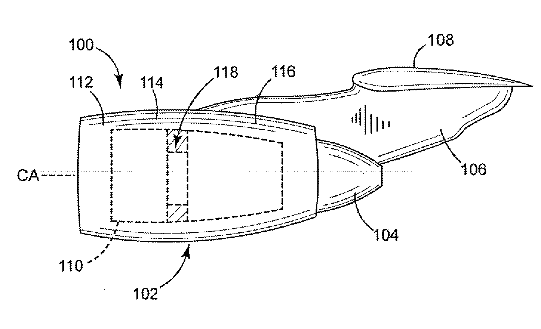
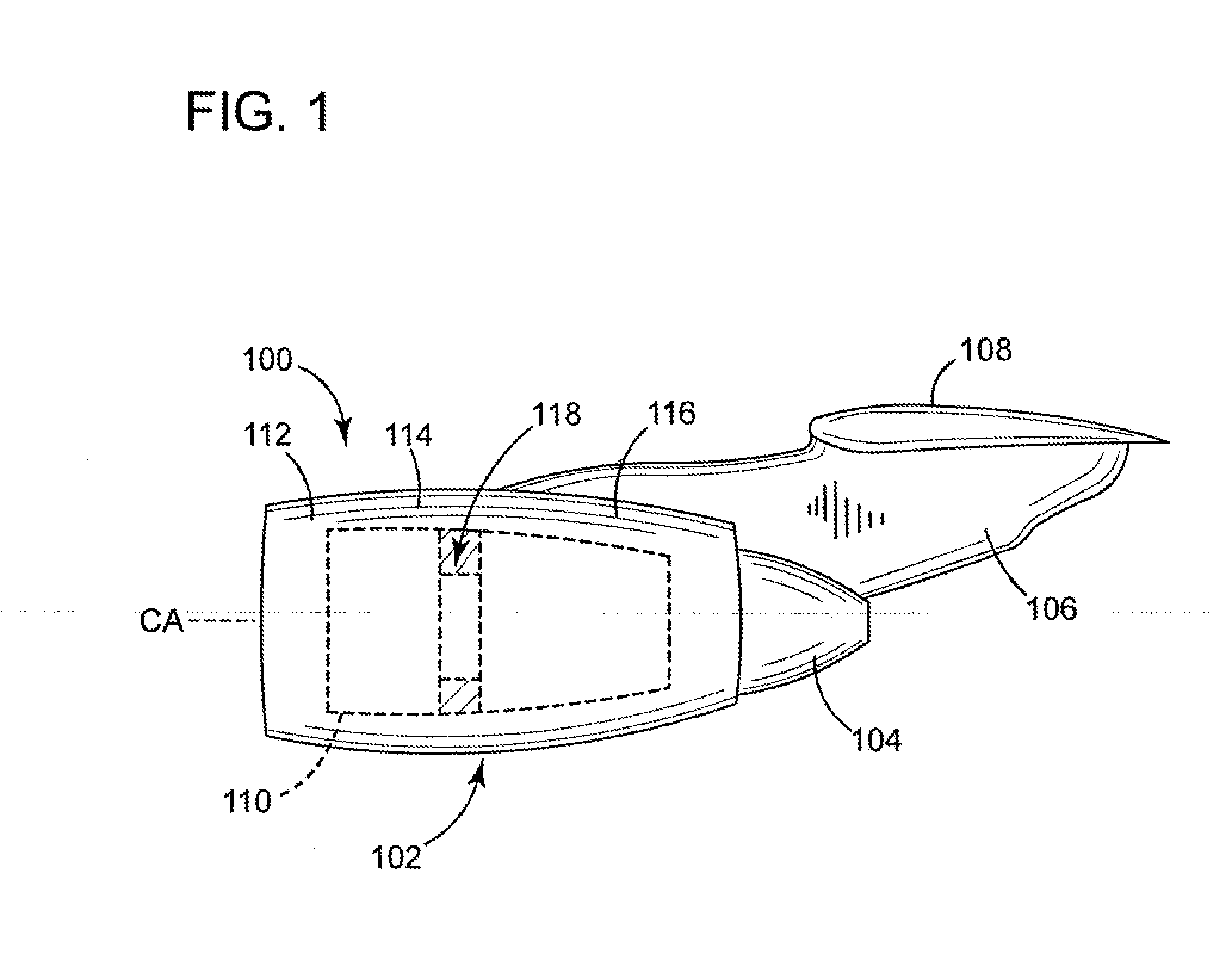
[0022]Referring to both FIGS. 1 and 2, one implementation of the repairs the inventors contemplate herein applies to aircraft engines. FIG. 1 depicts a schematic of a wing portion 100 of an aircraft that includes a nacelle 102, an exhaust nozzle 104, a pylon 106, and a wing 108. The nacelle 102 functions as an outer casing for a gas turbine engine (also “aircraft engine”), shown in general outline and identified by the numeral 110. The outer casing may comprise an inlet cowl 112, a fan cowl 114, and a thrust reverser 116. Of the many components and features that comprise the turbine engine 110, FIG. 1 focuses on illustrating one of them—a turbine nozzle 118, which is the subject of the following discussion. In one embodiment, the turbine nozzle 118 resides in the turbine section of the engine 110 and forms an annular ring that mounts about a central axis (CA) of the turbine engine 110. This annular ring directs air through the turbine engine 110. Depending on various factors such as...


PUM

PropertyMeasurementUnit
Shapeaaaaaaaaaa
Electrical conductoraaaaaaaaaa
Material propertiesaaaaaaaaaa

Abstract

A method for repairing a turbine nozzle having at least one vane disposed between an inner and an outer band. Embodiments of the method can comprise separating the inner band from the outer band and securing a replacement part to the inner band. In one embodiment, the methods accommodate replacement parts that include vanes with a base feature that comprises a non-airfoil shape and that integrates cooling features useful for operation of the turbine nozzle.

Description

BACKGROUND[0001]1. Technical Field[0002]The subject matter disclosed herein relates generally to gas turbine engines and, more particularly, to repair of turbine nozzle segments found in gas turbine engines such as aircraft engines.[0003]2. Description of Related Art[0004]A gas turbine engine includes a compressor that pressurizes air and delivers the pressurized air to a combustor. In the combustor, the air mixes with fuel and ignites to generate hot combustion gases. The combustion gases flow downstream to a turbine section, which transforms energy of the combustion gas flow to power the compressor and to provide useful work. An example of such gas turbine engines is an aircraft engine that can power an aircraft in flight.[0005]Aircraft engines may include stationary turbine nozzles that modify the gas flow and pressure within the turbine section. These changes can enhance engine performance. In one example, the aircraft engine has multiple turbine sections (or “stages”), where tu...

Claims


Application Information

Patent Timeline
IPC IPC(8): B23P6/00
CPCF01D5/005F01D9/02Y10T29/49318Y02T50/673F01D9/047Y02T50/60B23P6/002
Inventor BROWN, NATHANIEL PATRICKKNIGHT, GLENNGRADY, WAYNESTECKLER, MICHAEL
Owner GENERAL ELECTRIC CO
Learn More