Hydrostatic Circuits with Variable Charge and Variable Flushing Systems

a technology of hydrostatic circuits and flushing systems, which is applied in the direction of rotary clutches, couplings, fluid couplings, etc., can solve the problems of requiring premature replacement of hydrostatic fluids, excessive heat, and inability to meet the requirements of hydrostatic fluid replacemen

Active Publication Date: 2012-12-20
CATERPILLAR INC
View PDF8 Cites 5 Cited by
  • Summary
  • Abstract
  • Description
  • Claims
  • Application Information

AI Technical Summary

Benefits of technology

[0008]A closed hydrostatic circuit with a variable charge system and a variable flushing system in disclosed. The hydrostatic circuit includes a reservoir configured to hold the supply of fluid. The circuit also includes a variable displacement charge pump configured to supply charge fluid and pilot control fluid to the hydrostatic circuit. The circuit also includes an electronically controlled pressure regulating valve in communication with an output of the charge pump and linked to a controller. The circuit further includes a bidirectional variable displacement hydrostatic motor. The hydrostatic motor is connected to two input/output lines. The input/output line that has a higher pressure than the other input/output line serves as an input line while the input/output line having a lower pressure serves as an output line. The circuit also includes a flush valve in communication with the hydrostatic motor and both input/output lines. The flush valve and hydrostatic motor both are in communication with a flush orifice and a flush relief valve. When the pressure regulating valve causes the charge pump to operate at or near full capacity, fluid exits the flush valve and passes through both the flush orifice and the flush relief valve. Further, when the pressure regulating valve causes the charge pump to operate at or near a minimum capacity, fluid exits the flush valve and passes through the flush orifice without passing through the flush relief valve.
[0009]A refinement, a method of charging and flushing a closed hydrostatic circuit is disclosed. The method includes electronically controlling a variable displacement charge pump configured to supply charge fluid and pilot control fluid to a hydrostatic circuit. The method also includes electronically controlling a bidirectional variable displacement hydrostatic motor. Further, the method includes operating a motor at or near a maximum capacity and flushing fluid through a flush valve, a control orifice and a relief valve when

Problems solved by technology

When a hydrostatic transmission is operated under heavy loads for an extended period of time, it is possible for the oil, which is pumped in the closed circuit, to become heated to an extent which may not be desirable.
This heating occurs due to friction and other processes.
Hydrostatic fluid may degrade more quickly when maintained at excessive temperatures, thus requiring premature replacement of the hydrostatic fluid.
Further, elevated temperatures, hydrostatic fluid may lose certain lubricating properties including, but not limited to, viscosity.
When a hydrostatic fluid loses viscosity, it compromises the fluid's ability to prevent damaging wear to the hydrostatic machinery.
For example, current circuit flushing systems that incorporate a flush valve and

Method used


Image

  • Hydrostatic Circuits with Variable Charge and Variable Flushing Systems
  • Hydrostatic Circuits with Variable Charge and Variable Flushing Systems

Examples


Embodiment Construction

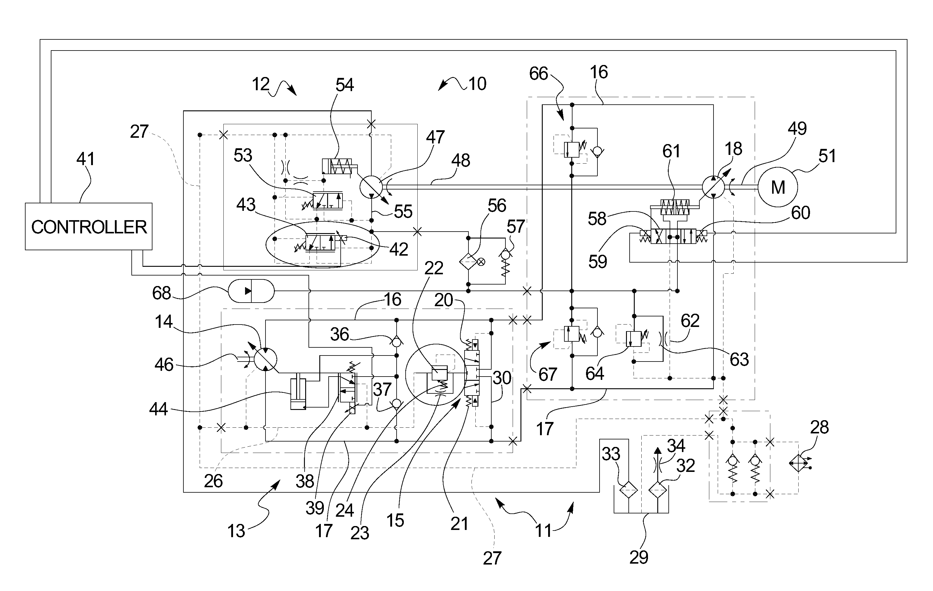
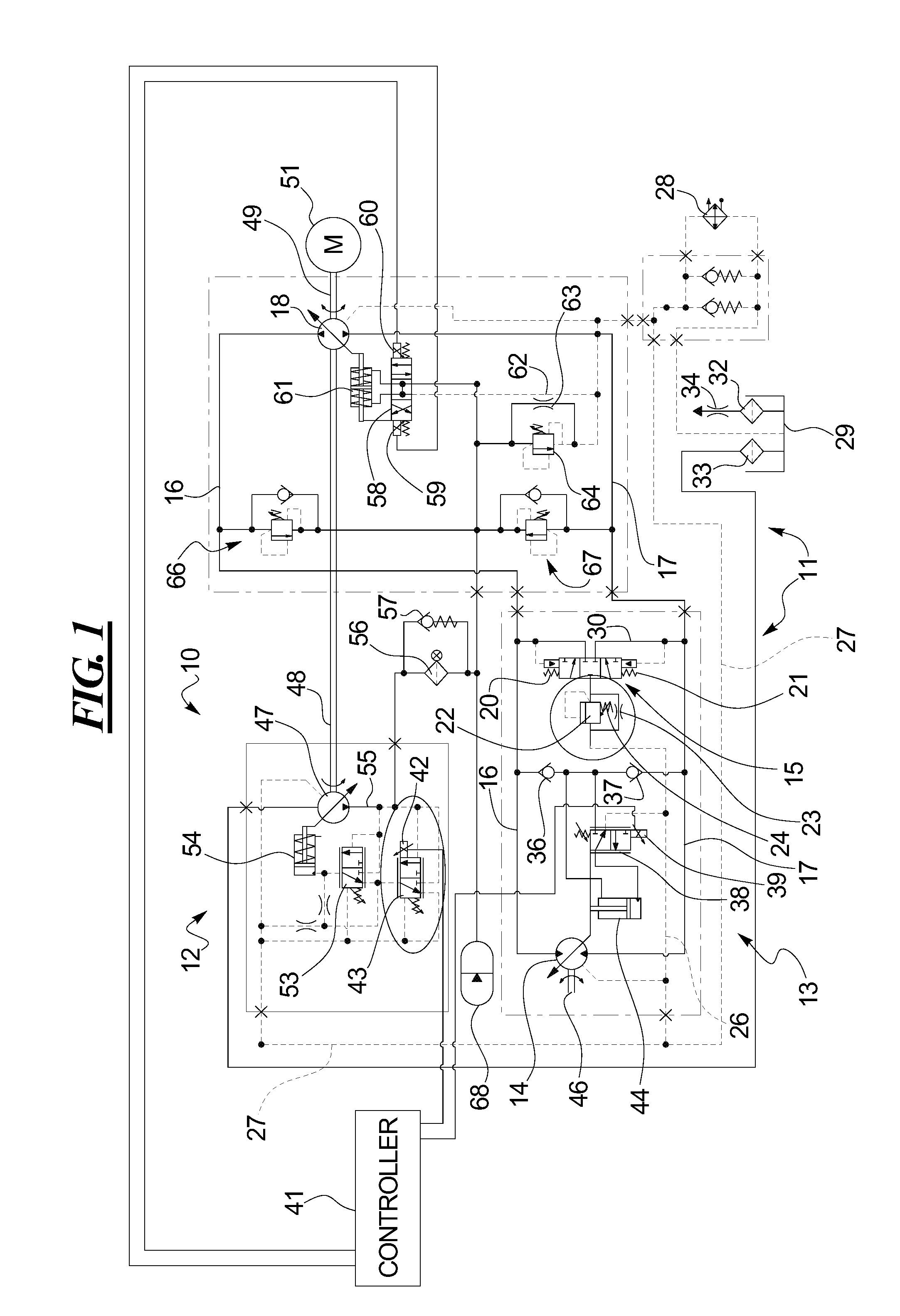
[0012]Use of the disclosed modulated circuit flushing flow may limit the power loss at low speed conditions to the lowest necessary loss and may still provide the requisite flushing and charge flow at high speed conditions.

[0013]Turning to FIG. 1, a closed hydrostatic circuit 10 is disclosed that includes a hydrostatic transmission 11 and a charge system 12. The hydrostatic transmission 11 also includes a flush system 13. The flush system 13 pumps cool pilot oil from the low pressure side of the bidirectional variable displacement hydrostatic motor 14 to maintain a sufficiently low temperature of the hydraulic oil, to cool the remainder of the hydrostatic circuit and to maintain the viscosity of the hydrostatic oil below about 12 sCt, although other oils of different viscosities may be used.

[0014]The flush system 13 includes a flush spool valve 15 which directs cooling flow from the cool or low pressure side of the hydrostatic transmission 11. Specifically, the hydrostatic transmiss...


PUM


Abstract

A closed hydrostatic circuit with variable charge and variable flushing systems is disclosed. A variable displacement charge pump is configured to supply charge fluid and pilot control fluid to the hydrostatic circuit. An electronically controlled pressure regulating valve is in communication with an output of the charge pump and is linked to a controller. When the hydrostatic control system detects a high hydraulic temperature condition, the electronically controlled pressure regulating valve, that is in communication with an output of the charge pump and that is linked to a controller, increases the charge pump flow. A bidirectional variable displacement hydrostatic motor is connected in parallel to two input/output lines. A flush valve is in communication with the hydrostatic motor and both input/output lines. The flush valve and hydrostatic motor are both in communication with the flush orifice and a flush relief valve. When the pressure regulating valve causes the charge pump to operate at or near a full capacity, fluid exits the flush valve and passes through both the flush orifice and the flush relief valve. In contrast, when the pressure regulating valve causes the charge pump to operate at a lower or near minimum capacity, fluid exits the flush valve and passes through the flush orifice only without passing through the flush relief valve.

Description

TECHNICAL FIELD[0001]This disclosure relates generally to variable charge and flushing systems for hydrostatic circuits and methods for charging and flushing hydrostatic circuits.BACKGROUND[0002]In the art of hydrostatics, oil or fluid is pumped by mechanical hydrostatic pumps for the purpose of causing a hydrostatic motor to revolve, a hydrostatic cylinder to extend, or for other useful purposes. A common aspect of many tractors, earthmoving machines and the like is a hydrostatic transmission. In its most basic form, a hydrostatic transmission consists of a hydrostatic pump which is normally driven by an internal combustion engine, and provides a source of pressurized oil flow which causes one of more hydrostatic motors to rotate. The rotation of these one or more hydrostatic motors will cause the machine to travel forward or reverse as commanded by the operator of the machine.[0003]In contrast, to hydraulic transmissions, hydrostatic transmissions operate in what is known as a clo...

Claims


Application Information

Patent Timeline
IPC IPC(8): F16D31/02F15B21/0423
CPCF16D31/00F16H61/4104F15B2211/7058F15B2211/20553F15B2211/611F15B21/042F15B21/0423
Inventor DEMICK, CHRISTOPHER J.DVORAK, PAUL A.SWICK, WILLIAM CHRISTOPHERGUYARD, VINCENTELLIOTT, CHRISTOPHER MARKPRUESS, CHRISTOPHER
Owner CATERPILLAR INC
Why Eureka
Try Eureka