
Image display device

Active Publication Date: 2012-12-20
AISIN SEIKI KK
View PDF4 Cites 33 Cited by
  • Summary
  • Abstract
  • Description
  • Claims
  • Application Information

AI Technical Summary

Benefits of technology

[0008]On the other hand, it is also desired to take advantage of the usefulness of displaying in the screen an assisting image such as a white line painted on the road surface for identifying a parking position or a grid for clarifying the distance to or the positional relationship relative to e.g. an obstacle present on the road surface. Then, it is desired that this assisting image such as a grid be displayed in such a form that allows unerring recognition by the driver of the distance between obstacle on the road surface or the like and the vehicle body.
[0028]With the above arrangement, in the perspective image, an area farther from the vehicle body is lowered in its visibility. So that, the perspective image adjacent the vehicle body is made clearer relative thereto. Hence, the grasping of the relative distance from e.g. an obstacle present adjacent the vehicle body is made easier. And, also, the perspective image of the far position will not hinder the visibility, either.

Problems solved by technology

However, with the above arrangement that displays a grid, a change in the traveling direction of the self vehicle results in displacement of the grid relative to the actual image.
Hence, in association with a steering operation, the grid will be displaced to the left or right relative to the background (actual image) captured by the camera, thus making it difficult to grasp the positional relationship between the grid and the background.
Especially, it was conceived that the relationship between the background and the grid will give a feeling of unnaturalness in case the steering operation involves acceleration or deceleration.
However, it was believed that as the area of this conspicuous color is displaced on the grid in association with a movement of the self vehicle, the mode of displaying will give feeling of unnaturalness.

Method used


Image

  • Image display device
  • Image display device
  • Image display device

Examples


Embodiment Construction

[0040]Modes of embodying the invention will be described with reference to the drawings.

[0041]In the instant mode of embodiment, there will be explained a control mode and control arrangement of an image display device configured to display a captured image of a rear camera 28 mounted at a rear end of a vehicle body 1 on a monitor 21 when the vehicle body 1 is to be reversed and to display also a perspective image Mp for facilitating grasping of the positional relationship between the vehicle body 1 and a white line or an obstacle or the like present on the road surface in superposition over the captured image.

[0042][Basic Arrangement]

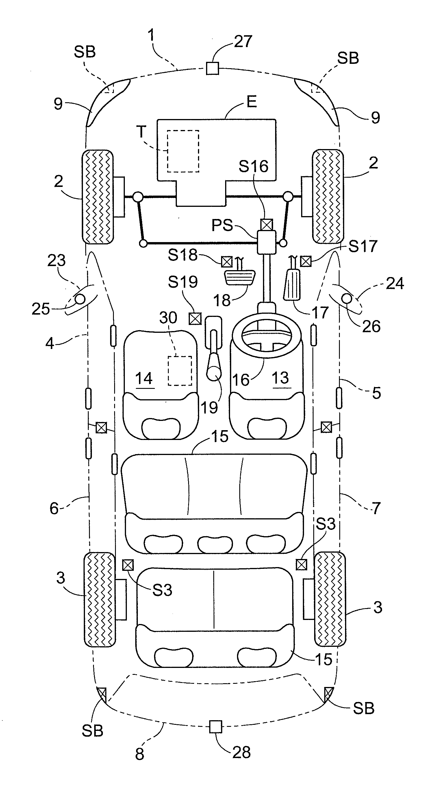
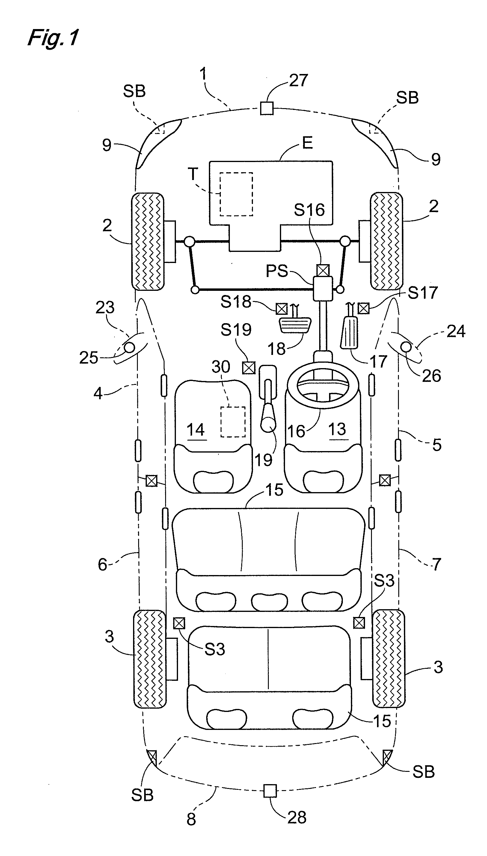
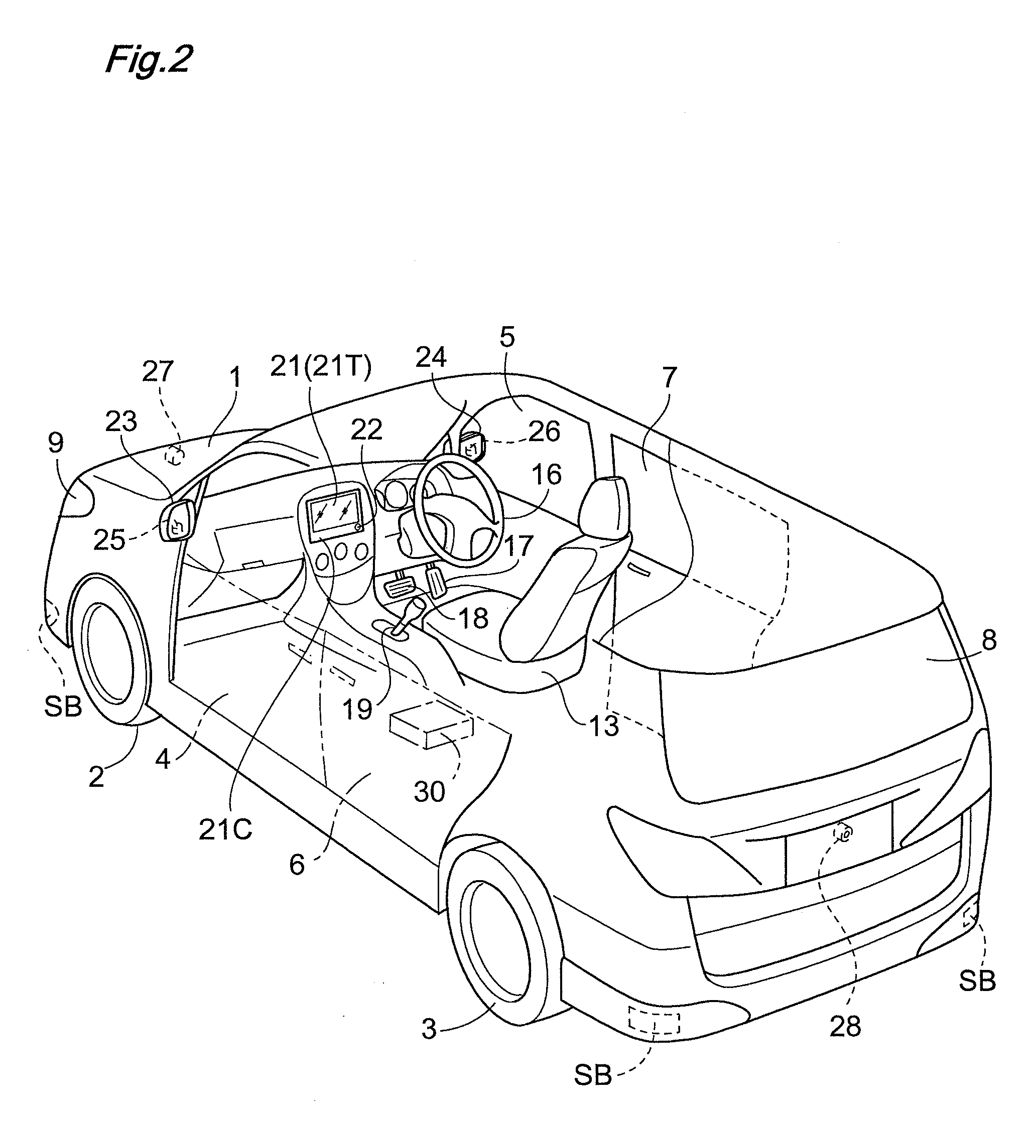
[0043]As shown in FIG. 1 and FIG. 2, the vehicle body 1 of a passenger car includes left and right front wheels 2 and left and right rear wheels 3. At front positions of the vehicle body 1, there are mounted a left front door 4 and a right front door 5 which can be opened / closed via hinges; and at rear positions of the vehicle body 1, there are mounted...


PUM


Abstract

Disclosed is an image display device that allows intuitive guidance of a vehicle body based on an assisting image displaced in a screen. The image display device includes an image processing section for displaying a captured image of a rear camera on a monitor. This image processing section includes a synthesis processing unit for displaying a perspective image providing a perspective in superposition over the captured image being displayed on the monitor and a display mode setting unit that realizes selection between a viewing field-fixed mode for displaying the perspective image in superposition with the perspective image being fixed within a viewing field of the monitor and a road surface-fixed mode for displaying the perspective image in superposition with allowing scrolling thereof in unison with a road surface.

Description

TECHNICAL FIELD[0001]The present invention relates to an image display device, more particularly to an image display device configured such that a camera mounted on a self-propelled vehicle of e.g. an automobile is used for capturing an image of the surrounding of the vehicle body and the image thus captured is displayed on a monitor disposed adjacent a driver's seat for assisting driving operation.BACKGROUND ART[0002]As an example of the image display device configured as above, Patent Document 1 discloses a device configured such that a monitor is caused to display a lattice-like, grid image providing a perspective in superposition over an actual image captured by a camera so as to allow monitoring of an area of viewing field that extends forwardly and to the left and right as being viewed from the driver.[0003]This Patent Document 1 discloses an arrangement for setting the grid image at such a height not to be overlapped with the image of any important object which may be present...

Claims


Application Information

Patent Timeline
IPC IPC(8): H04N7/18
CPCB60R1/00B60R2300/105B60R2300/305B60R2300/307B60R2300/607B60R2300/806H04N7/18B62D15/028B60R1/26
Inventor IKEDA, KEIGONAGAMINE, NOBORUMATSUBA, TOMOYUKI
Owner AISIN SEIKI KK
Learn More