Optical navigation module with capacitive sensor

a technology of optical navigation module and capacitive sensor, which is applied in the field of optical navigation module, can solve the problems of increasing the cost of optical navigation modul

Active Publication Date: 2012-12-20
CYPRESS SEMICON CORP
View PDF7 Cites 37 Cited by
  • Summary
  • Abstract
  • Description
  • Claims
  • Application Information

AI Technical Summary

Problems solved by technology

Although, this generally works well one problem is that each new device in which the optical navigation module is used requires a new mechanical and / or optical design and fine tuning of the optical navigation module.
Finally, the optical design to implement such a lift cutoff mechanism typically requires precision design and manufacturing processes, increasing the cost of the optical navigation module.

Method used


Image

  • Optical navigation module with capacitive sensor
  • Optical navigation module with capacitive sensor
  • Optical navigation module with capacitive sensor

Examples


Embodiment Construction

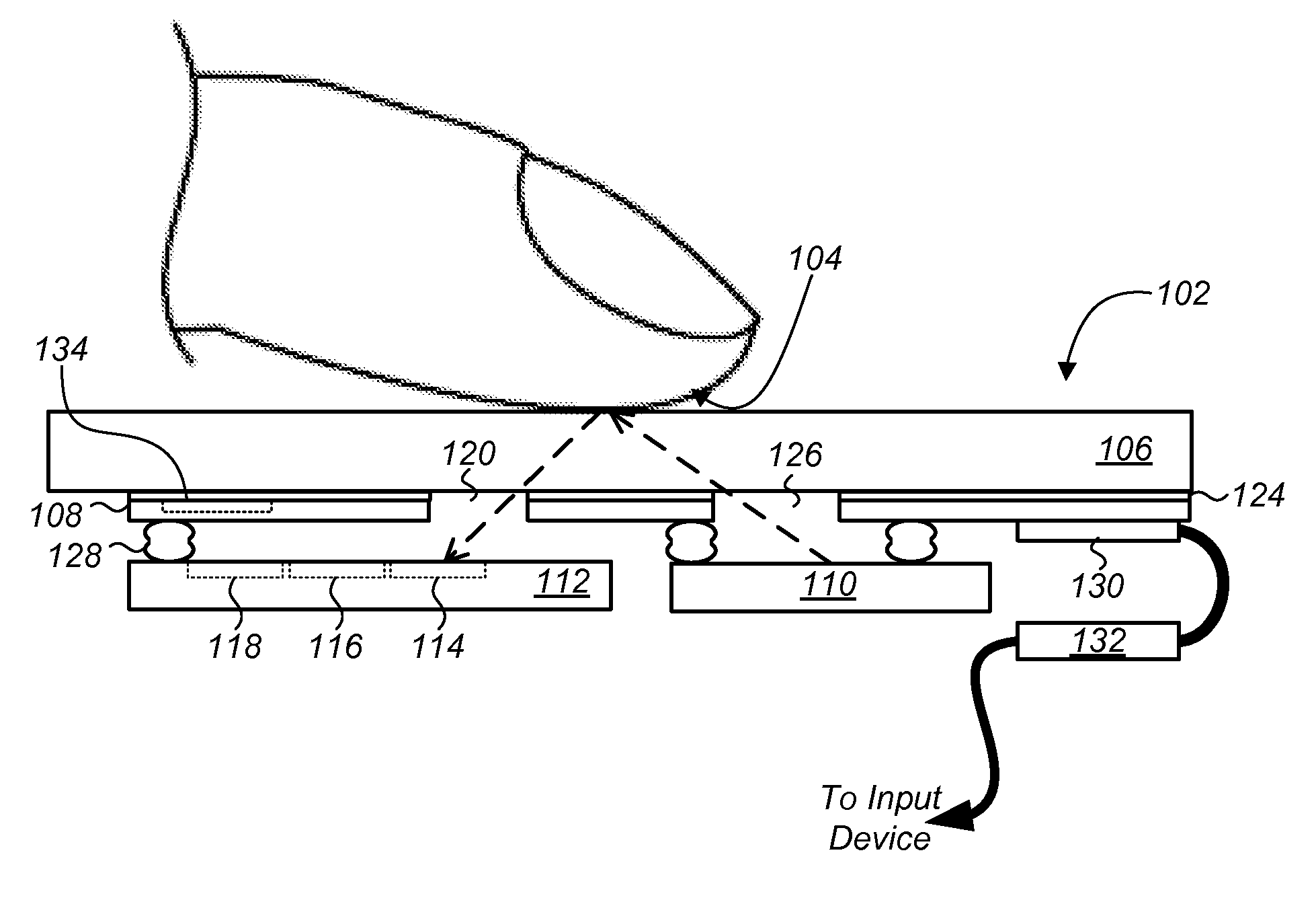
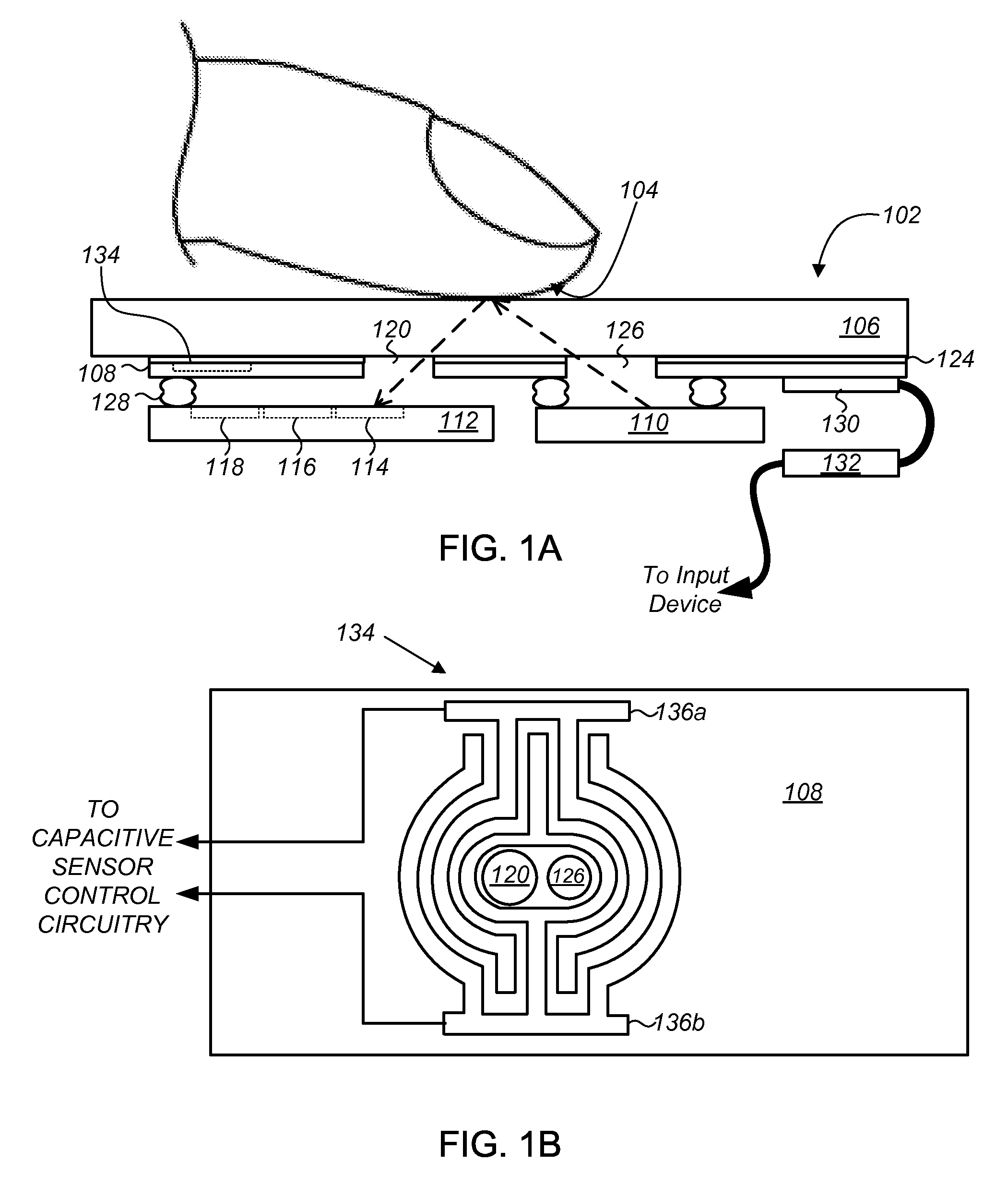
[0017]Optical navigation modules and methods are provided for use in an input device to sense relative movement between the optical navigation module and a tracking surface. In one embodiment, the optical navigation module comprises: (i) a light source to illuminate at least a portion of a surface relative to which the optical navigation module is moved; (ii) an integrated circuit (IC) including a photo-detector array (PDA) to detect a light pattern propagated onto the PDA from the surface, and a signal processor to translate changes in the light pattern propagated onto the PDA into data representing motion of the optical navigation module relative to the surface; and (iii) a substrate to which the light source and IC are mounted, the substrate including an aperture in a light path between the surface and the PDA.

[0018]In another embodiment, the optical navigation module is an optical finger navigation (OFN) module and comprises a capacitive sensor to detect a lift height separating...


PUM


Abstract

Optical navigation modules and methods of operating the same to sense relative movement between the optical navigation module and a tracking surface are provided. In one embodiment, the optical navigation module comprises: (i) a light source to illuminate at least a portion of a surface relative to which the optical navigation module is moved; (ii) an integrated circuit (IC) including a photo-detector array (PDA) to detect a light pattern propagated onto the PDA from the surface, and a signal processor to translate changes in the light pattern propagated onto the PDA into data representing motion of the optical navigation module relative to the surface; and (iii) a substrate to which the light source and IC are mounted, the substrate including an aperture in a light path between the surface and the PDA. Other embodiments are also disclosed.

Description

RELATED APPLICATIONS[0001]This claims the benefit of priority under 35 U.S.C. 119(e) to U.S. Provisional Patent Application Ser. No. 61 / 502,298, filed Jun. 28, 2011, and to U.S. Provisional Patent Application Ser. No. 61 / 497,939, filed Jun. 16, 2011, both of which are incorporated by reference herein.TECHNICAL FIELD[0002]The present disclosure relates generally to optical navigation module, and more particularly to optical finger navigation modules and methods of operating the same.BACKGROUND[0003]Data processing systems, such as personal computers, tablet computers, entertainment systems, game consoles, and cellular telephones, commonly include optical navigation sensors or modules for data input and / or cursor movement. Optical navigation modules generally include a light source to illuminate a tracking surface, and a sensor, such as a charge-coupled device (CCD), complementary metal-oxide-semiconductor (CMOS) imaging array, or a comb array, to capture an image or signal in light r...

Claims


Application Information

Patent Timeline
Patent Type & Authority Applications(United States)
IPC IPC(8): G01B11/14G01B11/22
CPCG01B11/002G01B11/22G06F3/0421G06F3/03547
Inventor MU, JINGHUISPURLOCK, BRETT ALANXU, YANSUNFRAME, JOHNZENG, KECAITODOROFF, BRIAN
Owner CYPRESS SEMICON CORP
Why Eureka
Try Eureka