[0009]The present invention is directed to methods of manufacturing and using customized low force orthodontic
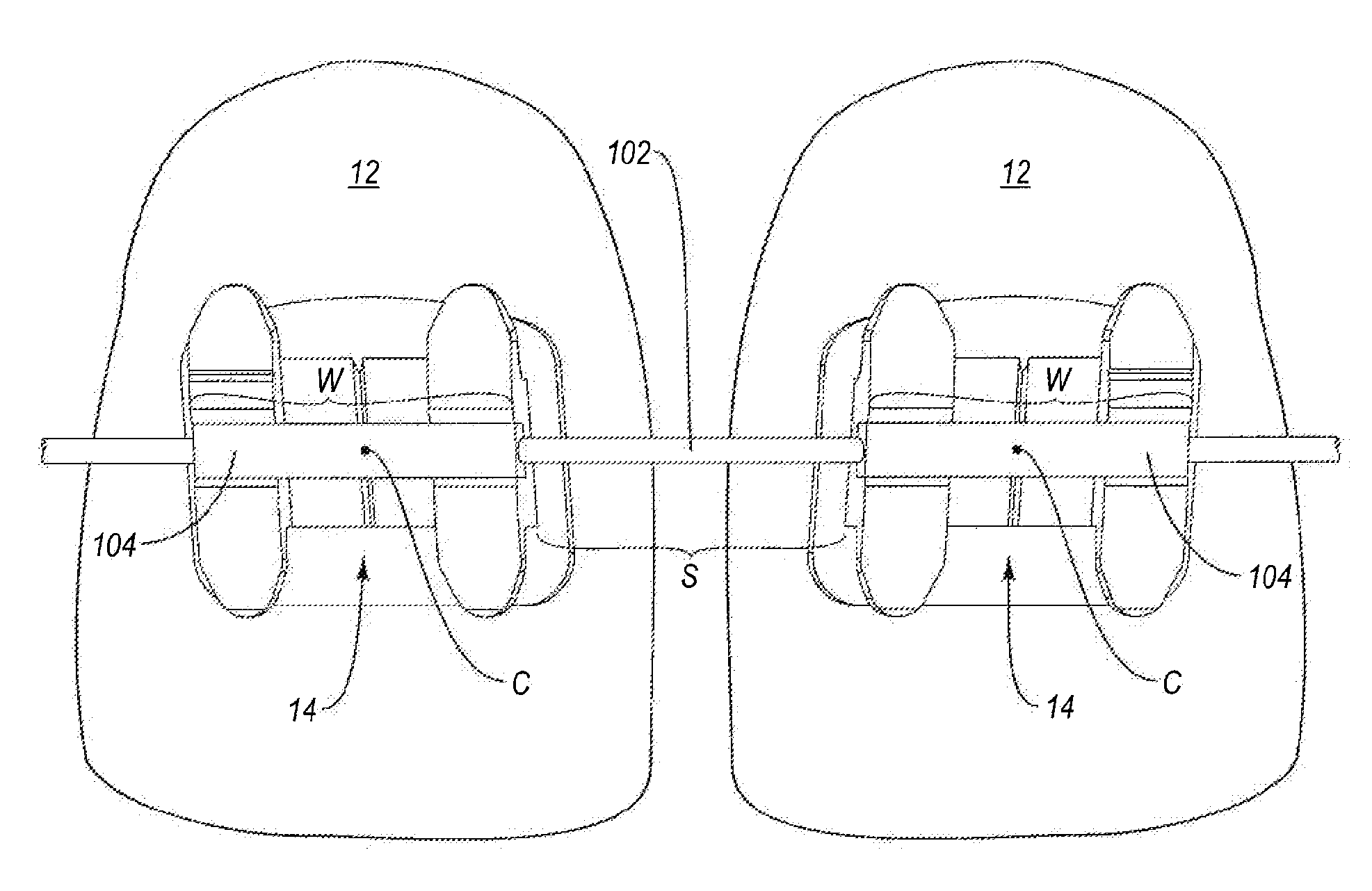
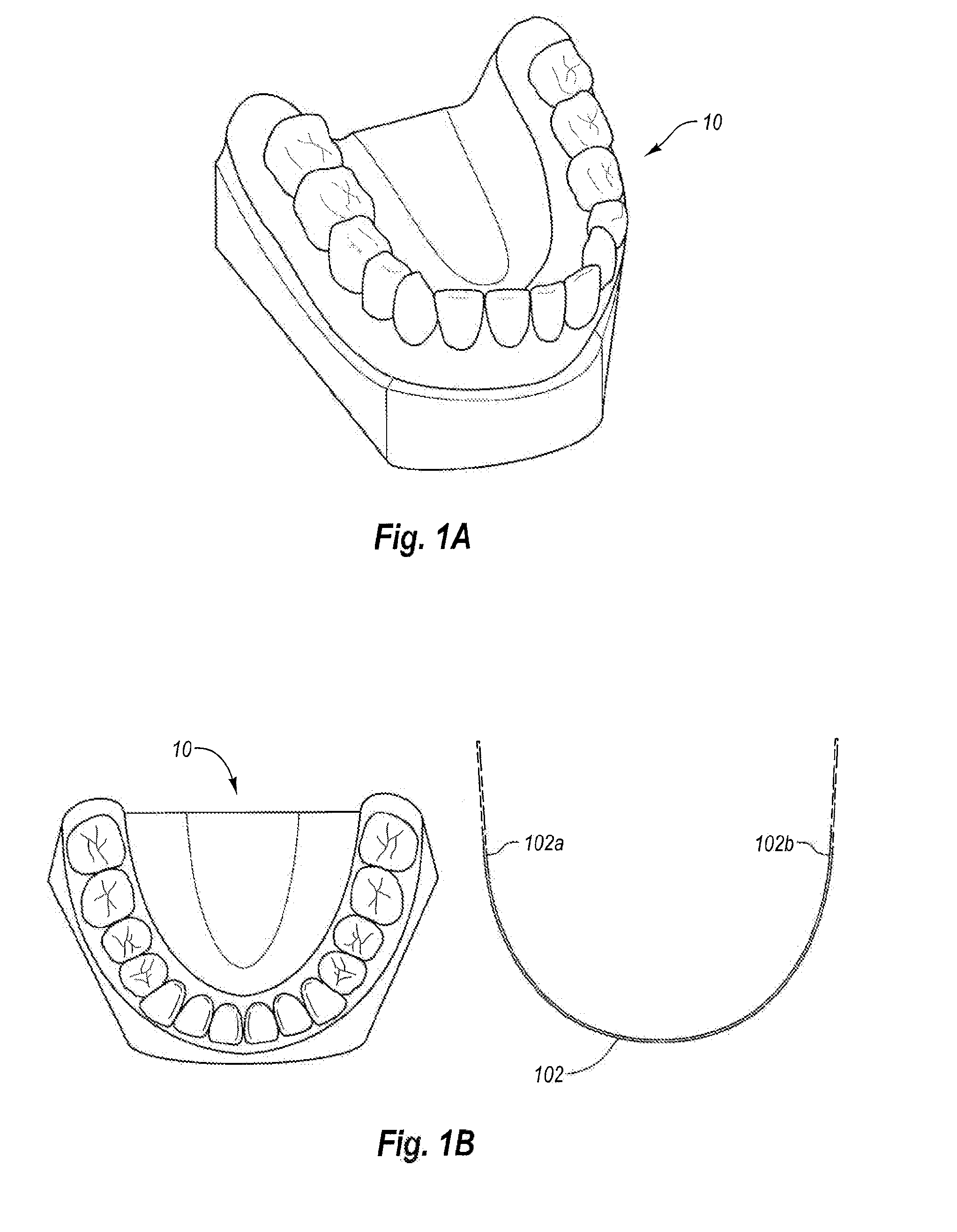
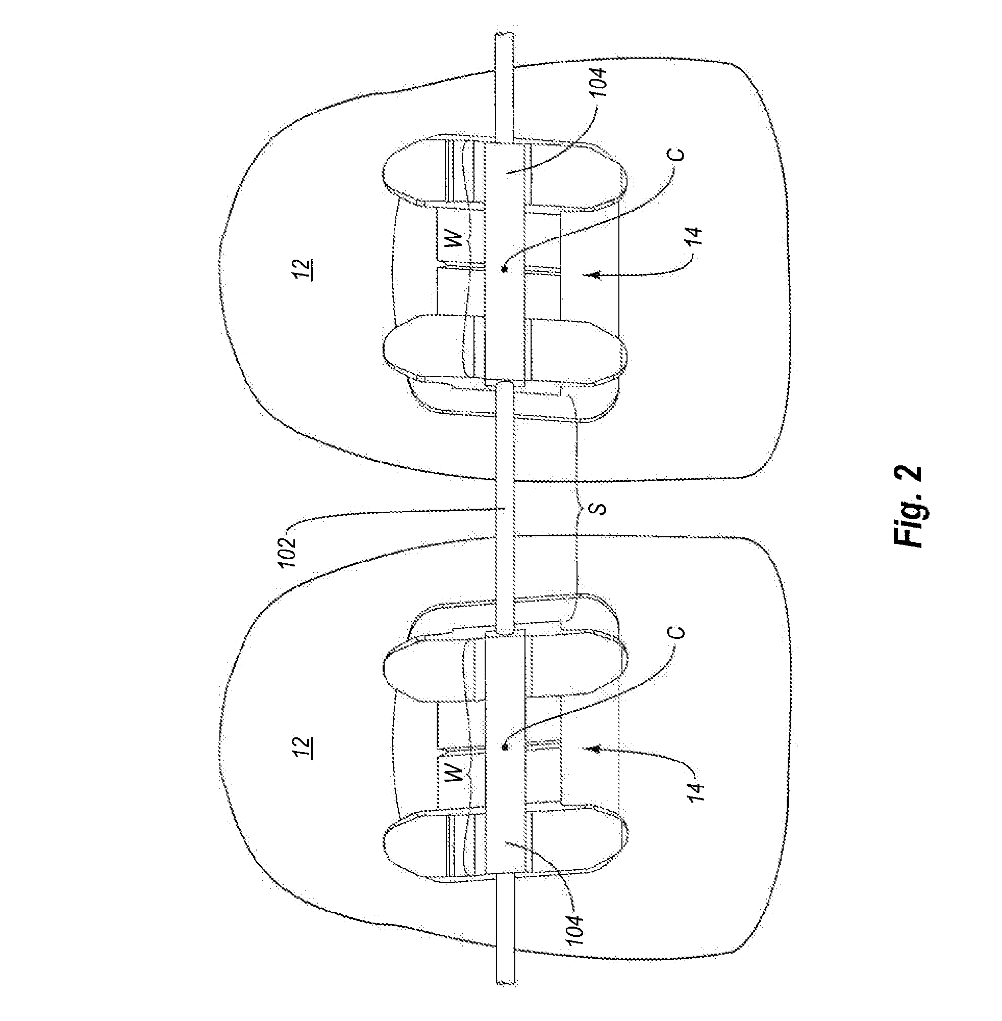
arch wires. The custom arch wires may be capable of applying torquing and / or other corrective forces early in orthodontic treatment. The customized low force arch wire includes a core wire formed of a material having shape memory that extends along a generally curved arch wire axis between a first end and a second end. The arch wire further includes a plurality of bracket engagement blocks disposed in spaced apart relationship along the length of the core wire. The spacing between each block (i.e., its particular position along the core wire length), as well as the length of the core wire are customized for the particular patient on which the arch wire is to be installed. Each engagement block is configured for placement within the slot of a corresponding orthodontic bracket with which it works to move the teeth in a desired direction. The engagement blocks are advantageously enlarged relative to the core wire (i.e., the cross-sectional width of the engagement blocks is greater than the cross-sectional width of the core wire), providing for better engagement between any given engagement block and its corresponding bracket slot as compared to if the engagement blocks were not present.
[0012]Regardless of the method of manufacture, the positioning of each engagement block along the core wire, including spacing between individual engagement blocks, as well as the overall length of the core wire itself, are customized to the particular patient. Such customization provides the best possible fit between the arch wire, engagement blocks, and brackets, improving the efficiency of the orthodontic treatment. In addition, the enlarged engagement blocks provide for increased surface contact and engagement between the bracket slot and arch wire than would otherwise occur if the blocks were absent. This improved engagement and reduced play of the arch wire in the bracket slot results in better application of corrective forces over a longer period of time. For example, a typical patient may visit the orthodontic practitioner about once every 6 weeks to have adjustments in the arch wire and / or brackets made. Application of corrective forces is best just after the adjustments are made. Because of play between the arch wire and bracket slot, a typical arch wire loses its ability to effectively transfer forces to the bracket and teeth as the teeth begin to move. Another adjustment is necessary.
[0013]Typically, the vast majority of corrective movement occurs for only about 2 weeks after adjustment. After this point, because of play between the arch wire and bracket slots, little movement occurs. This period of time, which may be as much as about 4 weeks of a 6 week adjustment interval, is mostly wasted. Corrective movement that lasts longer than this typical 2 weeks may be possible by using a larger, stiffer arch wire (which reduces play between the bracket slot and arch wire). However, stiffer arch wires are uncomfortable for the patient, and may also actually increase overall
treatment time as recent studies have shown that consistent low force application actually moves the teeth faster than high forces from stiffer arch wires.
[0014]In contrast, the thin core wire portions of the arch wire advantageously result in an arch wire with relatively low stiffness, so that the arch wire applies low corrective forces to the brackets and teeth. These characteristic low forces result in decreased
treatment time, as the teeth tend to move faster under application of such forces. This unique combination of low stiffness coupled with the enlarged engagement blocks allows for corrective forces to be relatively small, comfortable, and more efficient, providing excellent engagement (i.e., reduced play) between the arch wire and the bracket slots. This combination of better engagement, reduced play, and continuous low force advantageously allows for significant reduction in treatment times.
[0015]According to one embodiment, at least some of the engagement blocks will have a rectangular (e.g., square) cross-section. Some of the engagement blocks (e.g., corresponding to the rearward oriented teeth) can have a round (e.g., circular) cross-section. Rounded blocks do not provide a torque value but may be beneficial for use with teeth requiring no torque movement (e.g., molars and / or bicuspids) owing to reduced friction between rounded engagement blocks and brackets compared to rectangular blocks.

