Reducer of electric power steering system

Inactive Publication Date: 2012-12-20
HL MANDO CORP
View PDF15 Cites 20 Cited by
  • Summary
  • Abstract
  • Description
  • Claims
  • Application Information

AI Technical Summary

Benefits of technology

[0022]In accordance with the present invention, when compared with the prior art, it is possible to prevent a noise from being produced by a clearance between the inner rotor and the outer rotor, to simplify

Problems solved by technology

As a result, there is a problem in that when a vehicle loses the driving endurance thereof to a certain degree or when a large impact is reversely input through the steering shaft while the vehicle is being driven on a road, such as an unpaved road, a clearance between the inner and outer rotors

Method used


Image

  • Reducer of electric power steering system
  • Reducer of electric power steering system
  • Reducer of electric power steering system

Examples


Example

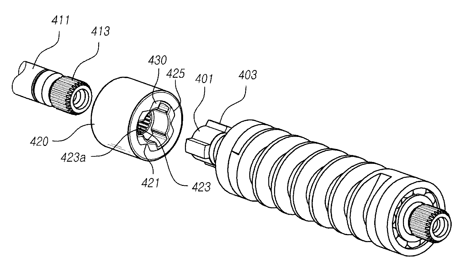
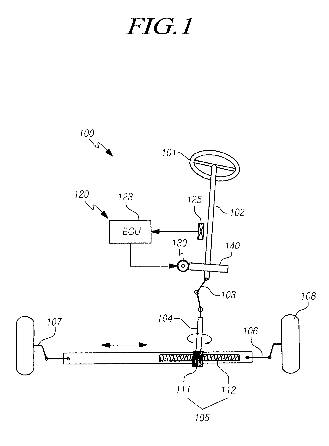
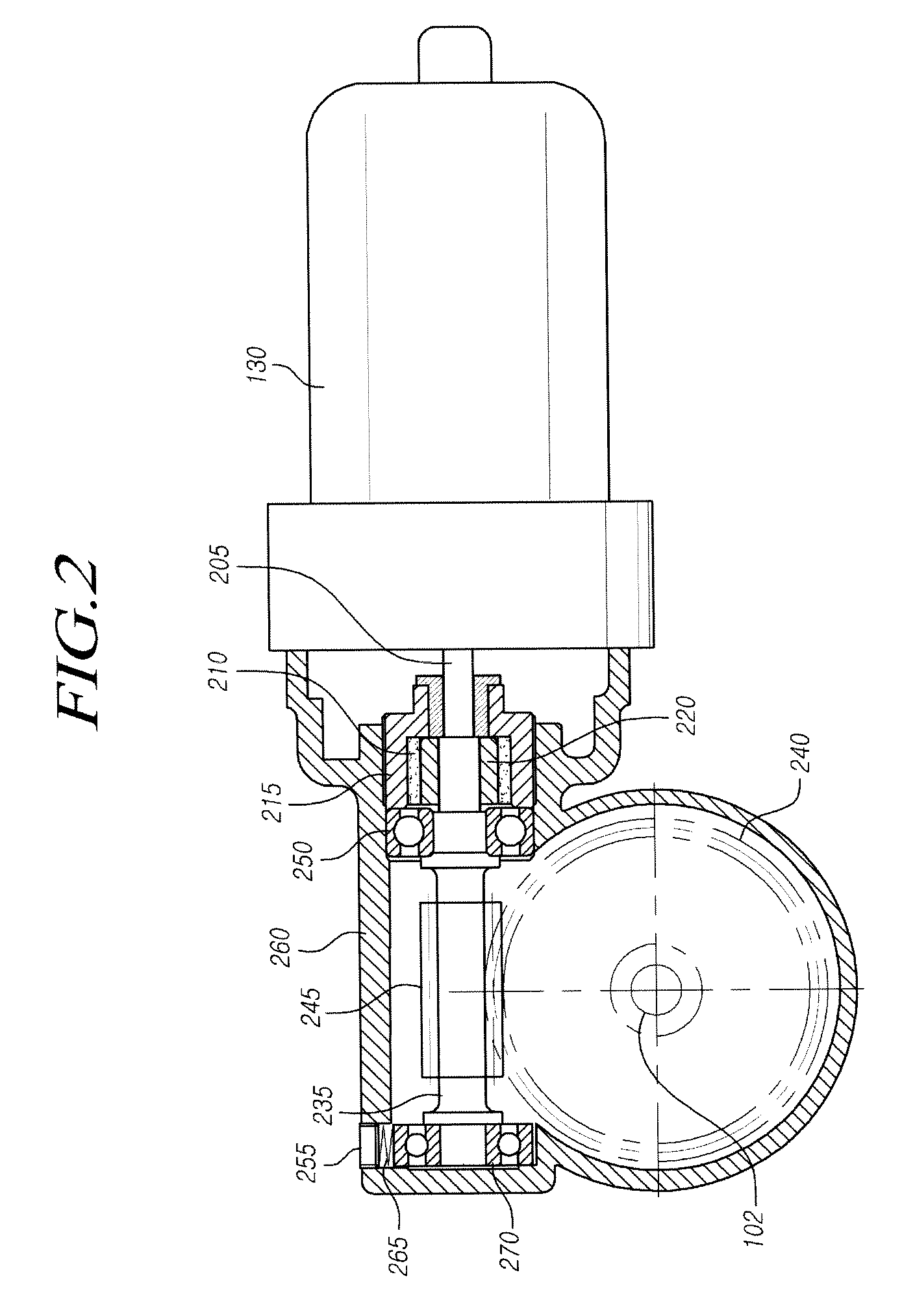
[0030]Hereinafter, exemplary embodiments of the present invention will be described with reference to the accompanying drawings. In the following description, the same elements will be designated by the same reference numerals although they are shown in different drawings. Further, in the following description of the present invention, a detailed description of known functions and configurations incorporated herein will be omitted when it may make the subject matter of the present invention rather unclear.

[0031]In addition, terms, such as first, second, A, B, (a), (b) or the like may be used herein when describing components of the present invention. Each of these terminologies is not used to define an essence, order or sequence of a corresponding component but used merely to distinguish the corresponding component from other component(s). It should be noted that if it is described in the specification that one component is “connected,”“coupled” or “joined” to another component, a t...


PUM


Abstract

The present invention relates to a reducer of an electric power steering system. By the system, it is possible to prevent a noise from being produced by a clearance between an inner rotor and an outer rotor. Further, since the steps of assembling the inner and outer rotors and applying grease are omitted, it is possible to simplify the assembling process of the reducer, to reduce the material costs, and to improve stability in assembling.

Description

CROSS-REFERENCE TO RELATED APPLICATION[0001]This application claims priority from and the benefit under 35 U.S.C. §119(a) of Korean Patent Application No. 10-2011-0059532, filed on Jun. 20, 2011, which is hereby incorporated by reference for all purposes as if fully set forth herein.BACKGROUND OF THE INVENTION[0002]1. Field of the invention[0003]The present invention relates to a reducer of an electric power steering system. More particularly, the present invention relates to a reducer of an electric power steering apparatus, which, when compared with a conventional reducer of an electric power steering apparatus, makes it possible to prevent a noise from being produced by a clearance between an inner rotor and an outer rotor, and to reduce the material costs as well as to improve stability in assembling since the steps of assembling the inner rotor and outer rotor and applying grease are omitted.[0004]2. Description of the Prior Art[0005]As generally known in the art, a steering ap...

Claims


Application Information

Patent Timeline
IPC IPC(8): F16D3/00
CPCB62D5/0409F16D3/02F16D3/10F16D3/74F16D3/76F16D2001/103F16D3/68B62D3/04B62D5/04B62D5/24
Inventor KIM, JONG HAN
Owner HL MANDO CORP
Why Eureka
Try Eureka