
Cooling scheme for an increased gas turbine efficiency

a technology of gas turbine efficiency and cooling scheme, which is applied in the direction of machines/engines, mechanical equipment, light and heating equipment, etc., can solve the problems of reducing the overall efficiency of the power plant, high nox emission levels, and relatively high life cycle costs

Active Publication Date: 2012-12-27
ANSALDO ENERGIA SWITZERLAND AG
View PDF4 Cites 27 Cited by
  • Summary
  • Abstract
  • Description
  • Claims
  • Application Information

AI Technical Summary

Problems solved by technology

As a result, there can arise relatively high NOx emission levels and relatively high life cycle costs.
This can ensure flame-free zones inside the burner but poses challenges in obtaining appropriate distribution of the fuel across the burner exit area.
The cross flow injection used in the known SEV-fuel injection devices (SEV fuel lances) can necessitate high-pressure carrier air supply, which can reduce the overall efficiency of the power plant.

Method used


Image

  • Cooling scheme for an increased gas turbine efficiency
  • Cooling scheme for an increased gas turbine efficiency
  • Cooling scheme for an increased gas turbine efficiency

Examples


Embodiment Construction

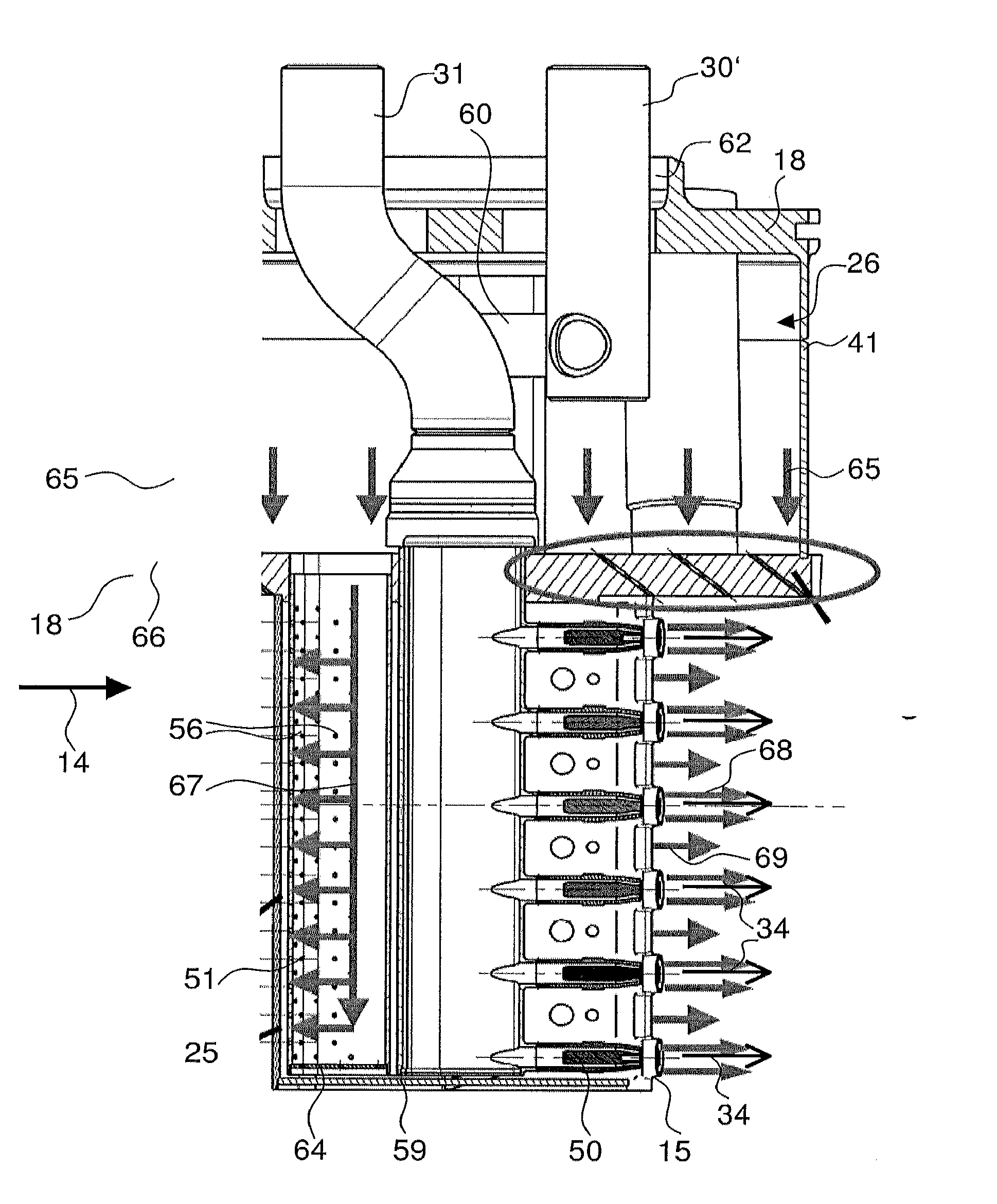
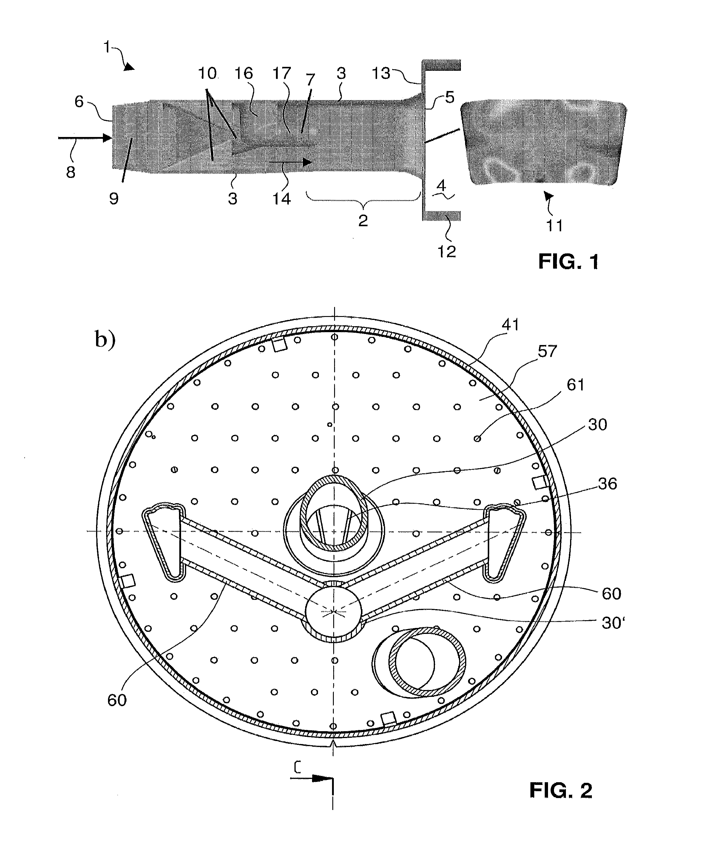
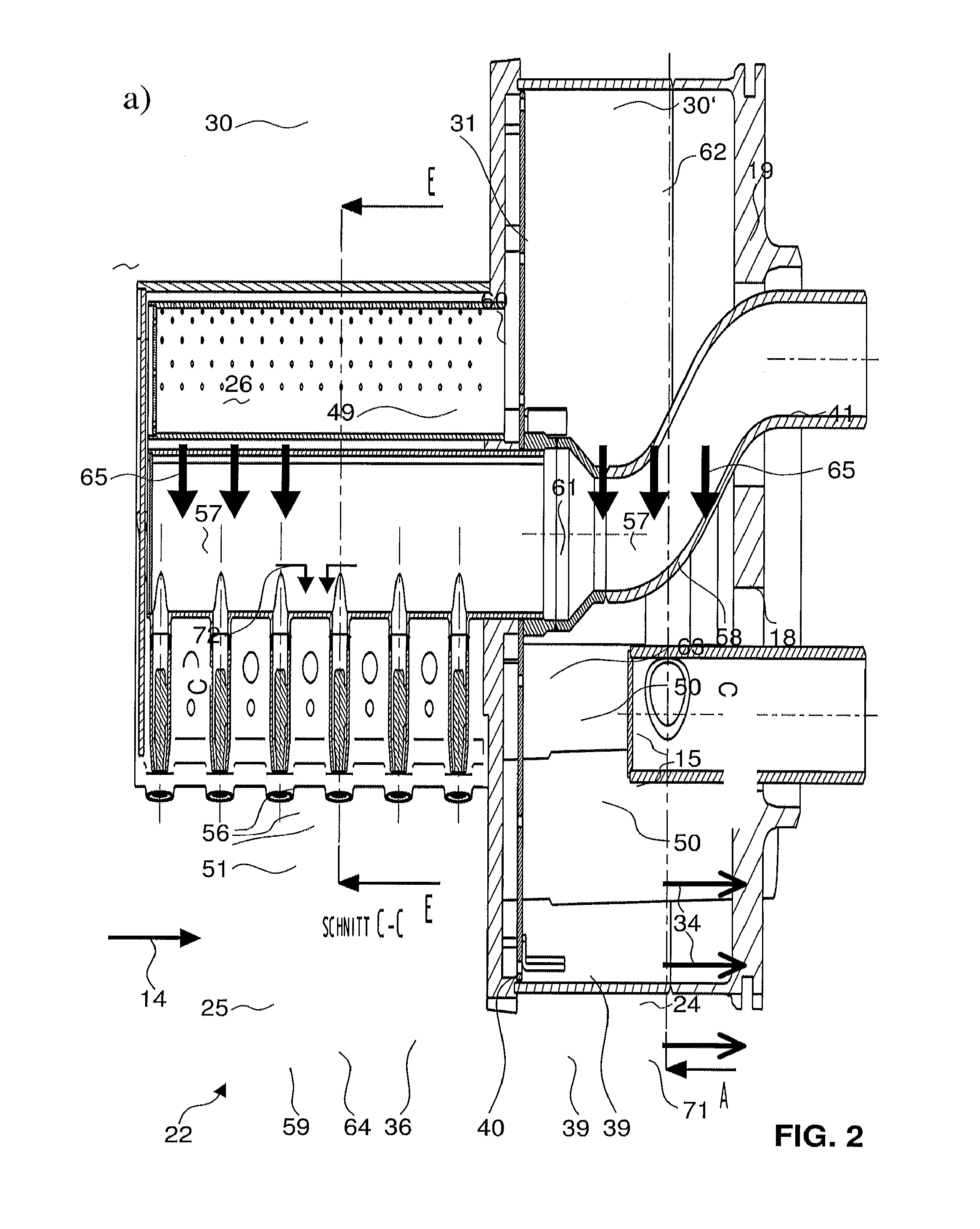
[0014]Exemplary embodiments of the present disclosure can provide an improved fuel injection device for combustion chambers of gas turbines. In particular an injection device is disclosed which can be operated with low pressure (carrier) air which at the same time acts as carrier air for fuel injection as well as cooling air.

[0015]Exemplary embodiments of the present disclosure relate to a burner for a combustion chamber of a turbine, for example, a gas turbine, with an injection device for the introduction of at least one gaseous and / or liquid fuel into the burner. The injection device has at least one body or lance which is arranged in the burner and extends into the burner cavity. The at least one body has at least two nozzles for introducing the at least one fuel into the burner. The burner can also be arranged as an element including more than one such body located next to each other, for example, a burner with three bodies located next to each other, each with a different incl...


PUM


Abstract

A burner for a combustion chamber of a turbine, with an injection device for the introduction of at least one gaseous and / or liquid fuel into the burner is proposed. The injection device has at least one body arranged in the burner with at least two nozzles for introducing the at least one fuel into the burner, the body being configured with a streamlined cross-sectional profile which extends with a longitudinal direction perpendicularly or at an inclination to a main flow direction prevailing in the burner. The carrier air plenum is provided with holes such that carrier air exiting through the holes impinges an inner side of a leading edge portion of the body.

Description

RELATED APPLICATION(S)[0001]This application claims priority as a continuation application under 35 U.S.C. §120 to PCT / EP2010 / 066513, which was filed as an International Application on Oct. 29, 2010 designating the U.S., and which claims priority to European Application 01888 / 09 filed in Europe on Nov. 7, 2009. The entire contents of these applications are hereby incorporated by reference in their entireties.FIELD[0002]A fuel lance is disclosed for a burner for a primary combustion chamber of a turbine or secondary combustion chamber of a turbine with sequential combustion having a first and a secondary combustion chamber, for the introduction of at least one gaseous and / or liquid fuel into the burner. Modifications to a cooling scheme of the fuel lance are proposed to increase the gas turbine engine efficiency as well as to simplify the design.BACKGROUND INFORMATION[0003]In order to achieve improved efficiency, a high turbine inlet temperature is used in standard gas turbines. As a...

Claims


Application Information

Patent Timeline
IPC IPC(8): F23R3/36F02C7/18
CPCF23D2214/00F23R3/34F23R3/283F23R3/20
Inventor WINKLER, ANTONBENZ, URSTHEUER, ANDRELAUFFER, DIANEPOYYAPAKKAM, MADHAVAN
Owner ANSALDO ENERGIA SWITZERLAND AG
Learn More