
Elevator

a technology of elevators and lifts, applied in the field of elevators, can solve problems such as the falling of metal ropes, and achieve the effect of preventing the movement of the diverting pulley and good energy economy of the elevator

Inactive Publication Date: 2012-12-27
KONE CORP
View PDF13 Cites 6 Cited by
  • Summary
  • Abstract
  • Description
  • Claims
  • Application Information

AI Technical Summary

Benefits of technology

[0013]The invention is based on the concept that if the overspeed governor rope of an elevator is formed to be such that its longitudinal power transmission capability is based on non-metallic material, more particularly on non-metallic fibers, the rope can be lightened and as a result of the lightness the energy efficiency of the elevator can be improved. What is now invented is that although the overspeed governor rope forms a very small part of the moving masses of the elevator, by forming the rope in a specified way, considerable savings can be achieved even though inexpensive metal is replaced with a more expensive material.
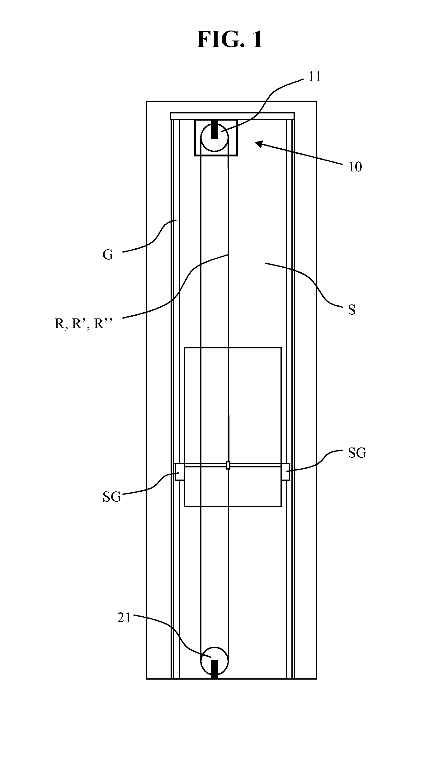
[0014]In a basic embodiment of the concept according to the invention the elevator comprises at least an elevator car and means for moving the elevator car, preferably along guide rails, and an overspeed governor arrangement, which comprises an overspeed governor rope, which moves according to the movement of the elevator car, and which overspeed governor rope is connected to a brake arrangement that is in connection with the elevator car such that with the overspeed governor rope force can be transmitted to the brake arrangement for shifting the brake comprised in the brake arrangement into a braking position. The rope comprises a power transmission part or a plurality of power transmission parts, for transmitting force in the longitudinal direction of the rope, which power transmission part is essentially fully of non-metallic material. Thus an energy-efficient elevator is achieved, because the mass of the parts that move along with the movement of the car is lower than before. Thus also the force required for slowing down / stopping the rope is small, and the force needed to bring about the force is likewise small. Acting on the rope is thus simple, and e.g. achieving sufficient traction can be less problematic than before. Thus a larger proportion than before of the force acting on the rope is transmitted to the car to the brake arrangement. In this way also the other aforementioned advantages can be achieved.
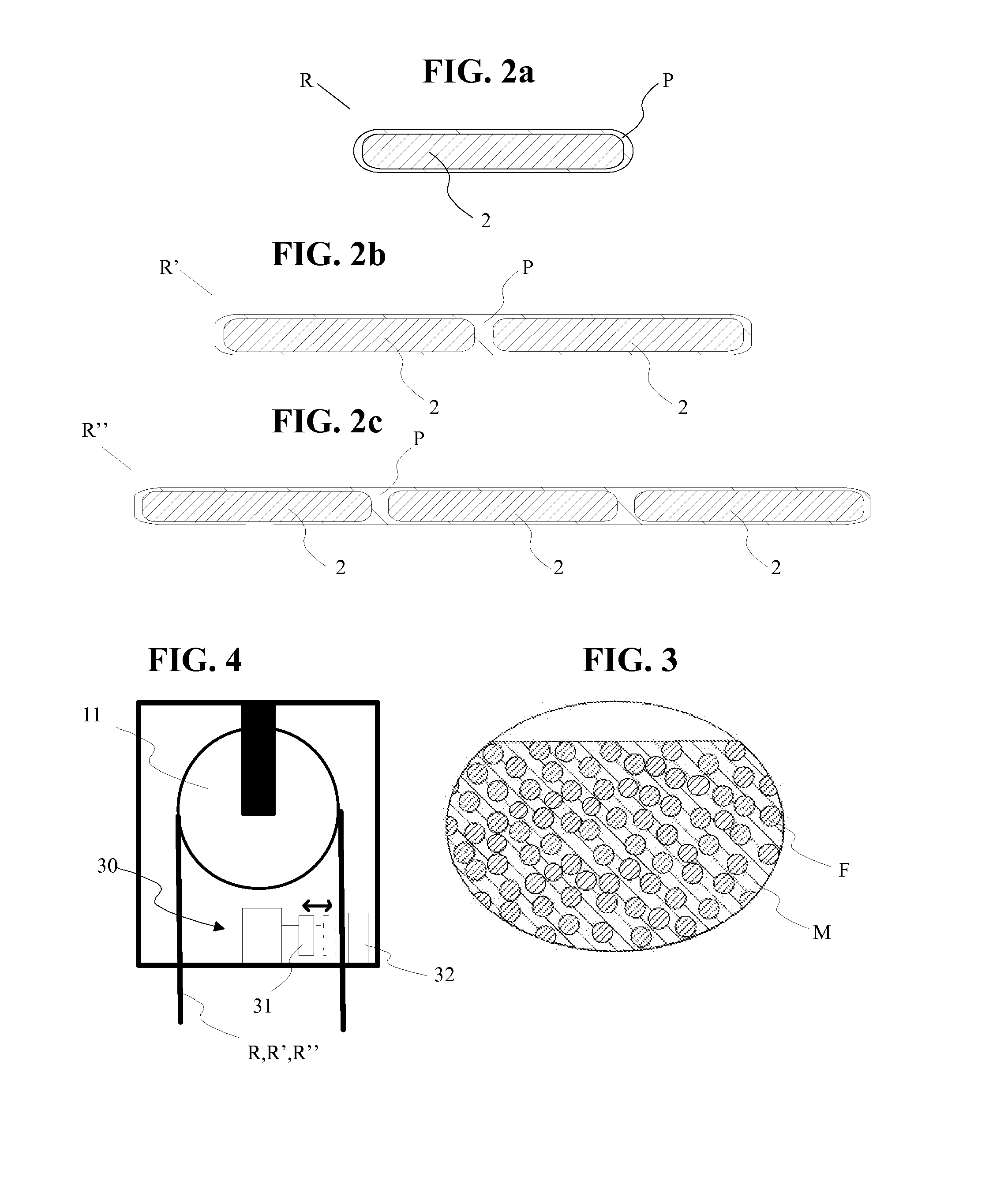
[0015]In a more refined embodiment of the concept according to the invention the overspeed governor rope passes around at least one diverting pulley comprised in the overspeed governor arrangement, bending at the point of the diverting pulley around an axis that is in the width direction of the rope, and the width of the overspeed governor rope is greater than the thickness. One advantage, among others, is that the bending radius of the rope can be reduced without losing supporting cross-sectional area. As a consequence, the rope can be manufactured from rigid material, the elongation properties of which would otherwise prevent an advantageous bending radius. The use of a rigid material reduces creeping problems, e.g. dimension problems caused by creeping that is caused by tensioning of the rope. The rope can thus also be formed to comprise a larger surface area than before, via which the speed of the rope can be acted on, e.g. for braking the rope. In this way the rope can be acted on more reliably than before without damaging the non-metallic parts of the rope. More particularly, a large surface area enables rapid deceleration / stopping of the rope without slipping problems, e.g. in an overspeed situation.

Problems solved by technology

A problem in solutions according to prior-art is that the strength properties of metal in relation to its mass are such that the rope must be formed to be large in terms of its mass.
Yet another problem has been the creeping of metal ropes.

Method used


Image

  • Elevator
  • Elevator
  • Elevator

Examples


Embodiment Construction

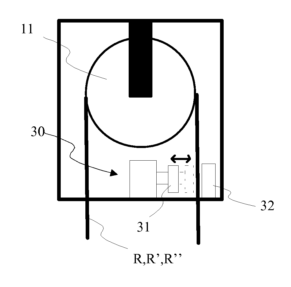
[0059]FIG. 1 presents an elevator according to the invention, which comprises an elevator car C and means for moving the elevator car (not presented) along guide rails G, and an overspeed governor arrangement, which comprises an overspeed governor rope R, which moves according to the movement of the elevator car (e.g. along with the movement of the elevator car, preferably moved by the elevator car) and passes around the diverting pulleys (11,21) comprised in the overspeed governor arrangement, bending at the point of each diverting pulley around an axis that is in the width direction of the rope. The overspeed governor rope R,R′,R″ is separate from the means that move the elevator car and is connected to a brake arrangement that is in connection with the elevator car C such that with the overspeed governor rope force can be transmitted to the brake arrangement of an elevator car for shifting the brake SG of the elevator car into a braking position, in which position the brake SG in...


PUM

PropertyMeasurementUnit
thicknessaaaaaaaaaa
thicknessaaaaaaaaaa
densityaaaaaaaaaa

Abstract

Elevator, which comprises at least an elevator car and means for moving the elevator car, preferably along guide rails, and an overspeed governor arrangement, which comprises an overspeed governor rope, which moves according to the movement of the elevator car, and which overspeed governor rope is connected to a brake arrangement that is in connection with the elevator car such that with the overspeed governor rope force can be transmitted to the brake arrangement for shifting the brake comprised in the brake arrangement into a braking position. The rope comprises a power transmission part or a plurality of power transmission parts, for transmitting force in the longitudinal direction of the rope, which power transmission part is essentially fully of non-metallic material.

Description

CROSS REFERENCE TO RELATED APPLICATIONS[0001]This application is a continuation of International Application Number PCT / FI2011 / 000020 filed Apr. 12, 2011 and claims priority to Finish Application Number 20100149 filed Apr. 12, 2010, the entire contents of each of which are hereby incorporated herein by reference.FIELD OF THE INVENTION[0002]The object of the invention is an elevator, preferably an elevator applicable to moving people.BACKGROUND OF THE INVENTION[0003]In the overspeed governor arrangements in prior-art elevators, the elevator is provided with a safety gear, the tripping of which occurs from the triggering of the overspeed governor. The conventional solution is that when the speed of the elevator increases to a limit value set in advance for the overspeed governor, the overspeed governor trips the safety gear via the same rope as the rope via which the overspeed governor monitors the speed of the elevator. Publication U.S. Pat. No. 4,653,612 describes the structure and ...

Claims


Application Information

Patent Timeline
Patent Type & Authority Applications(United States)
IPC IPC(8): B66B5/04B66B7/06
CPCB66B5/04B66B7/06D07B1/04D07B1/22D07B2205/2014D07B2205/2039D07B2201/2046D07B2205/206D07B2205/3003D07B2205/3007D07B2501/2007D07B2205/2057D07B2801/10D07B2801/16D07B2201/2016B66B5/18B66B5/044B66B7/062
Inventor VALJUS, PETTERIPELTO-HUIKKO, RAIMO
Owner KONE CORP
Learn More