
High temperature electrolyzer (HTE) having a stack of electrolysis cells and improved operating reliability and high efficiency

a high-temperature electrolyzer and stack technology, which is applied in the direction of electrolysis components, electrolysis processes, electrochemical generators, etc., can solve the problems of large quantity of hydrogen burning, complicated gas management, and increased risk of possible leakag

Active Publication Date: 2012-12-27
COMMISSARIAT A LENERGIE ATOMIQUE ET AUX ENERGIES ALTERNATIVES
View PDF17 Cites 27 Cited by
  • Summary
  • Abstract
  • Description
  • Claims
  • Application Information

AI Technical Summary

Benefits of technology

[0037]The advantage of the second embodiment compared to the first embodiment is that it is possible for the different functions to be kept completely independent, namely supply of electrical power to the stack, supply of minimally hydrogenated or unhydrogenated steam to the stack, supply of minimally hydrogenated or unhydrogenated steam to the interior of the sealed case, and clamping by compression of the stack of electrolysis cells. By this means, it is in fact possible to ensure and control each of these functions more precisely.
[0040]According to an advantageous embodiment, the sealed casing consists of a case including a base and a cover which are securely attached to one another, and where the stack of elementary electrolysis cells is assembled between two plates, the lower plate of which is resting on the base of the case through an electrical insulator. By this means the risk of electrical short-circuit of the stack of cells is prevented.
[0041]It is also possible to incorporate the clamping function of the electrolyser directly in the case: this has the advantage that there is thus no requirement to make additional openings and the associated seals, which are required with clamping means outside the case. Clamping means are thus fitted between the upper plate and the cover of the case, where the clamping means are designed to provide a determined contact force between the interconnecting plates and the electrodes.

Problems solved by technology

At the current time, management of the gases is therefore complicated since two different gas inlets must be provided, one at the cathode and the other at the anode, together with two different gas outlets, one of which is also at the cathode and the other at the anode.
This complication leads to an increased risk of possible leaks, of their immediate impacts, with the final consequence of more or less substantial impairments of efficiency and / or possible breakages in the electrolyser which may make it inoperative.
3: substantial risk: a large quantity of hydrogen may burn.
Fewer improved seals must therefore be made, compared to a conventional electrolyser.

Method used


Image

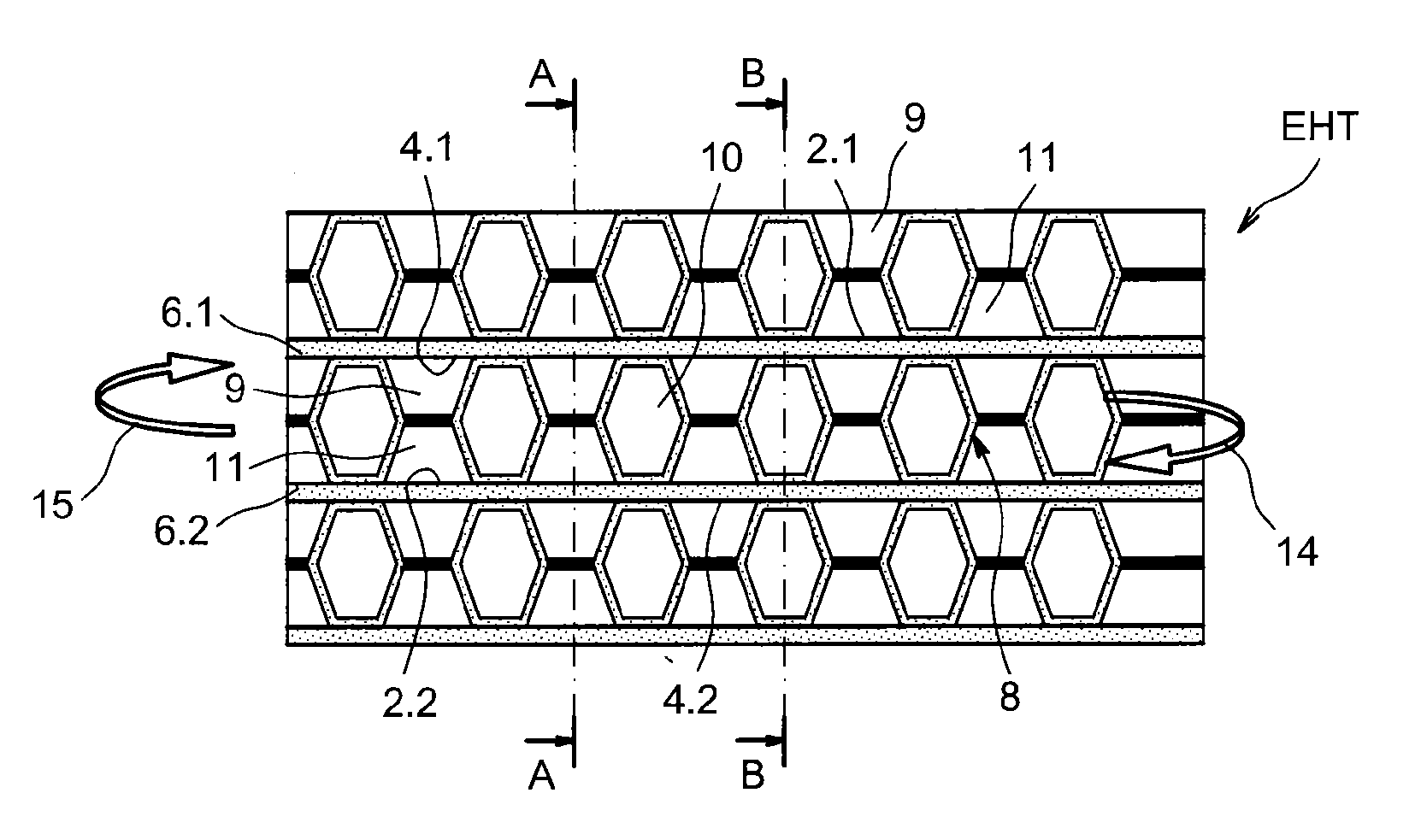
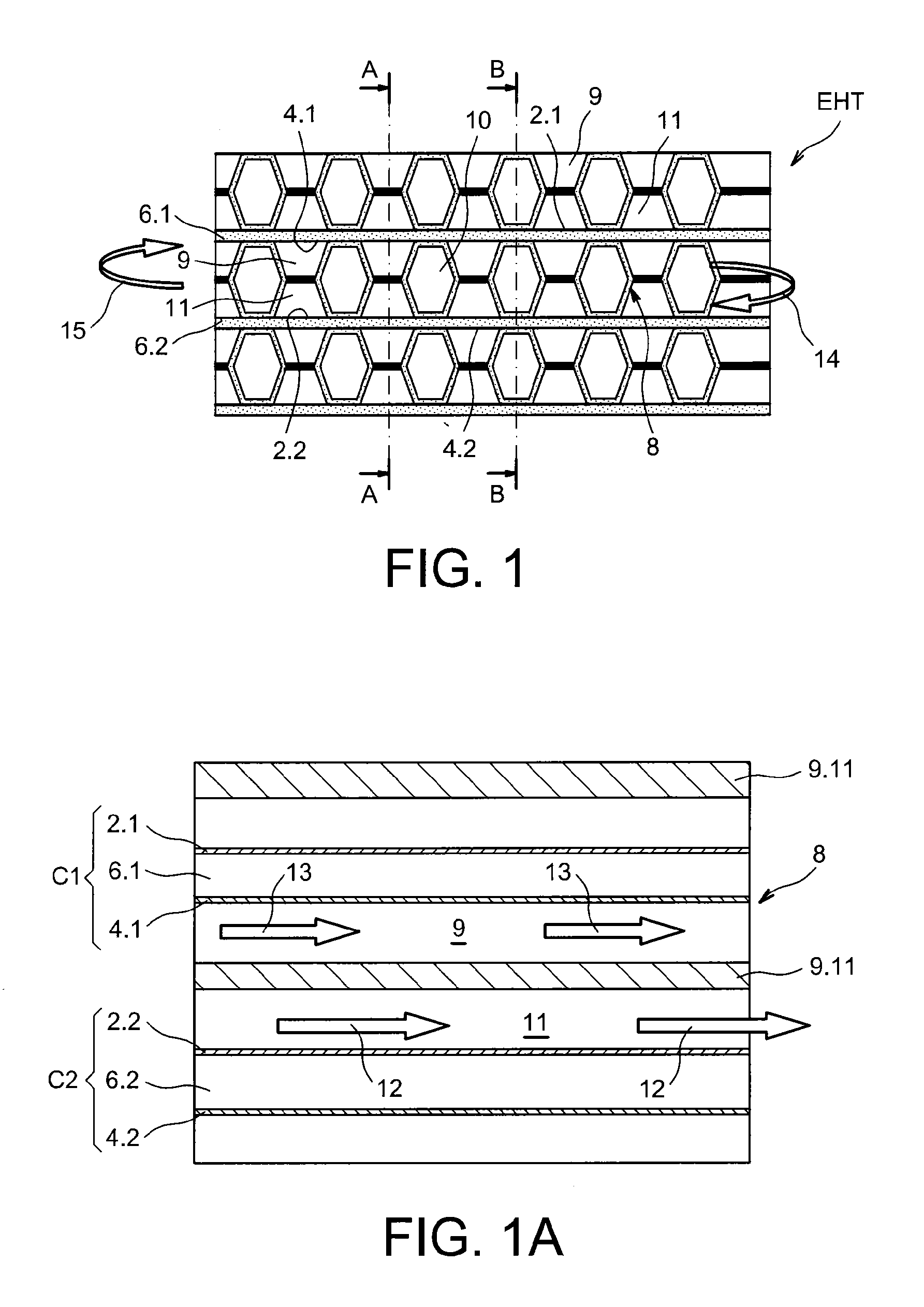
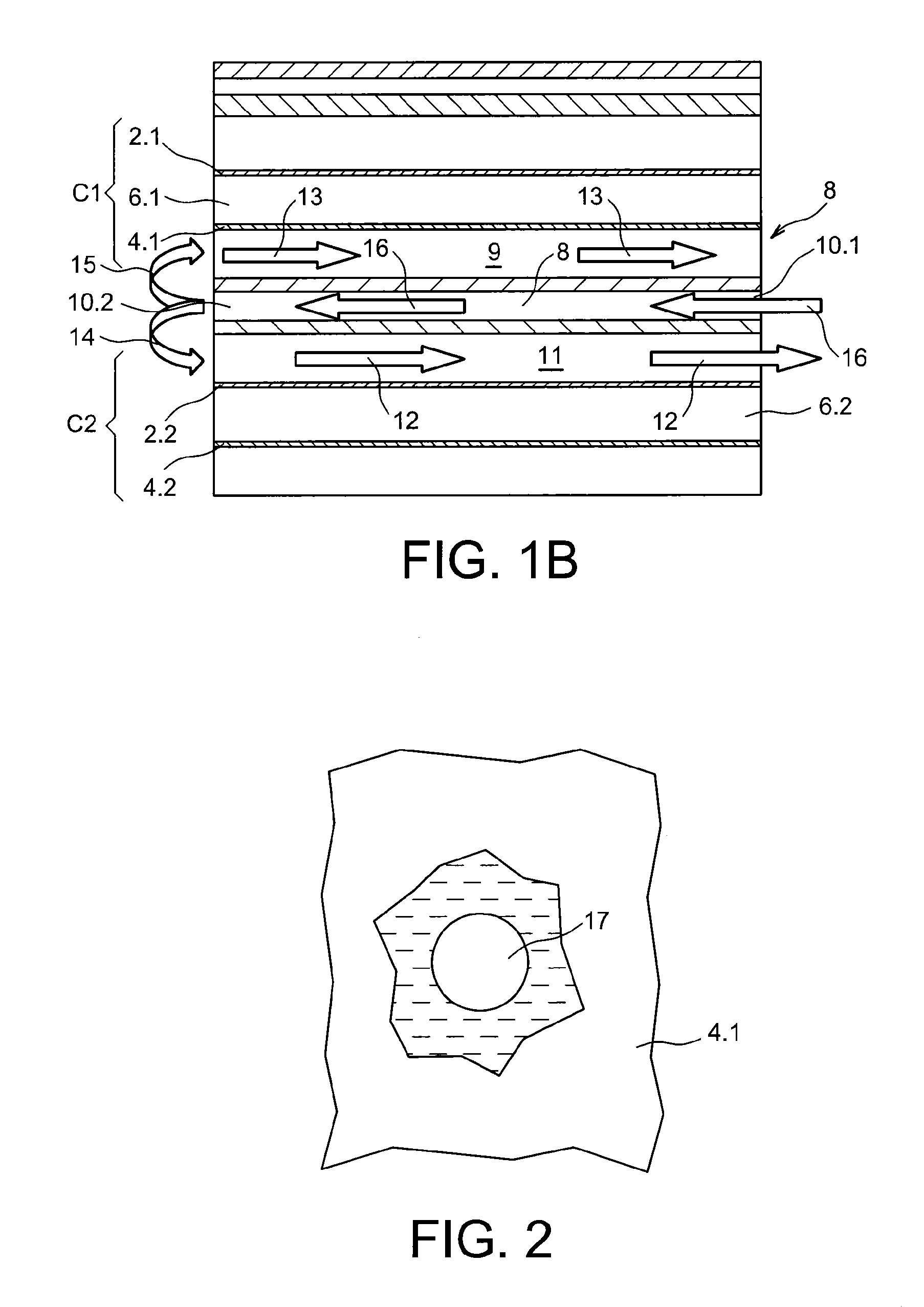
  • High temperature electrolyzer (HTE) having a stack of electrolysis cells and improved operating reliability and high efficiency
  • High temperature electrolyzer (HTE) having a stack of electrolysis cells and improved operating reliability and high efficiency
  • High temperature electrolyzer (HTE) having a stack of electrolysis cells and improved operating reliability and high efficiency

Examples


first embodiment

[0029]To accomplish this, the object of the invention is a module for high-temperature electrolysis, including[0030]a sealed casing designed to contain steam containing at most 1% hydrogen, or an inert gas,[0031]a stack of elementary electrolysis cells, each formed of a cathode, an anode and an electrolyte sandwiched between the cathode and the anode, where at least one interconnecting plate is fitted between two adjacent elementary cells, in electrical contact with an electrode of one of the two elementary cells and an electrode of the other of the two elementary cells, where the interconnecting plate includes at least one cathodic compartment and at least one anodic compartment for gas to flow respectively in the cathode and in the anode, and where the stack of electrolysis cells is housed in the sealed casing,

[0032]in which the sealed casing consists of a case including a base and a cover which are securely attached to one another, where the stack of elementary electrolysis cell...

second embodiment

[0035]According to the invention the lower plate is resting directly on the base of the case, and the clamping means are designed to apply a load by gravity from outside the case, on the upper plate, through a bellows which is securely attached, in a sealed manner, to the cover of the case, and where an electrically insulating part which enables the load applied to be transmitted is fitted inside the case between the bellows and the upper plate.

[0036]Advantageously, the connections are fitted through the base of the case without any electrical contact with their attachment to the case, and allowing electrical connection to the stack of electrolysis cells from outside the case.

[0037]The advantage of the second embodiment compared to the first embodiment is that it is possible for the different functions to be kept completely independent, namely supply of electrical power to the stack, supply of minimally hydrogenated or unhydrogenated steam to the stack, supply of minimally hydrogena...


PUM

PropertyMeasurementUnit
Fractionaaaaaaaaaa
Temperatureaaaaaaaaaa
Forceaaaaaaaaaa

Abstract

A high-temperature module for electrolysis of water with improved operational safety, in which steam containing at most 1% hydrogen can be made to flow simultaneously in each cathode and in each anode, as a draining gas, of a stack of cells. The stack of cells is housed in a sealed case and a mechanism for clamping by compression of the stack is included. The risks of leaks likely to cause impairments of efficiency and breakages of all or part of a stack EHT electrolyser are reduced, while a high level of efficiency is provided due to the fact that satisfactory electrical conduction is maintained by compression of the stack.

Description

TECHNICAL FIELD[0001]The present invention concerns a module with a sealed enclosure combined with a reactor for high-temperature electrolysis (EHT) of water, of the type having a stack of cells, with a view to producing hydrogen.[0002]The module with sealed enclosure according to the invention allows improved operational safety of high-temperature electrolysers, by reducing the risks of leaks which may cause impairments of efficiency and / or possible breakages of all or part of its elements.[0003]The invention relates more particularly to maintenance of the high efficiency of such a module. The term “high temperatures” is understood to mean, in the context of the invention, temperatures at least equal to 450° C., and typically of between 600° C. and 1000° C.PRIOR ART[0004]A high-temperature electrolyser (EHT), also called high-temperature steam electrolysis (EVHT), of the type with a stack, includes multiple elementary electrolysis cells formed by a cathode and an anode separated by...

Claims


Application Information

Patent Timeline
IPC IPC(8): C25B9/18C25B15/08
CPCC25B1/04C25B9/04H01M8/248Y02E60/366C25B1/12C25B9/18Y02E60/36Y02E60/50C25B9/65C25B9/70C25B9/05
Inventor LE GALLO, PATRICKSARRO, JEAN-LUCPLANQUE, MICHELREYTIER, MAGALI
Owner COMMISSARIAT A LENERGIE ATOMIQUE ET AUX ENERGIES ALTERNATIVES
Learn More