Ice Trap for Straw

a straw and ice trap technology, applied in the field of drinking cups and glasses, can solve the problems of only working with cylindrical glasses or cups, diluting the drink, and hastening the melting, and achieve the effect of preventing sliding

Inactive Publication Date: 2012-12-27
MERINO JAIME ANGEL
View PDF7 Cites 18 Cited by
  • Summary
  • Abstract
  • Description
  • Claims
  • Application Information

AI Technical Summary

Benefits of technology

[0060]2. a mechanism located at the apex of the cone that holds the straw in place. The straw is prevented from sliding along the axis of the cone by frictional or mechanical means.
[0061]The retaining force exerted by the holding mechanism is adjusted to be weak enough to allow a user to push a conventional straw through the hole in the cone, yet large enough to prevent the cone from being pushed upward by the buoyancy of the ice after the straw has been inserted through the hole and is held stationary. Optionally the straw is also prevented by mechanical means from yawing or pitching with respect to the axis of the cone.

Problems solved by technology

This approach has the unfortunate result of diluting the drink when the ice melts and of wasting ice.
Existing art also has the disadvantage of keeping the ice dispersed in the liquid, rather than clumped together, thus hastening its melting.
Because of the buoyancy of the ice, this approach can only work with cylindrical glasses or cups and when the disk has essentially the same diameter as the cylinder.
The problem with this approach is that the net is an inverted cone and therefore, the ice which is buoyant, congregates at its rim rather than at its center where the straw intake is located, thereby defeating the purpose of keeping the ice as close to the straw intake as possible.
There are several problems with this approach: 1) The user must assemble the straw, washers and net; 2) even though the net is prevented by the washers from sliding along the axis of the straw, it can still yaw and pitch with respect to the straw; 3) washers can be difficult to attach and to slide along the straw without damaging the straw; and 4) loose parts can fall in the drink, thereby posing a danger.

Method used


Image

  • Ice Trap for Straw
  • Ice Trap for Straw
  • Ice Trap for Straw

Examples


Embodiment Construction

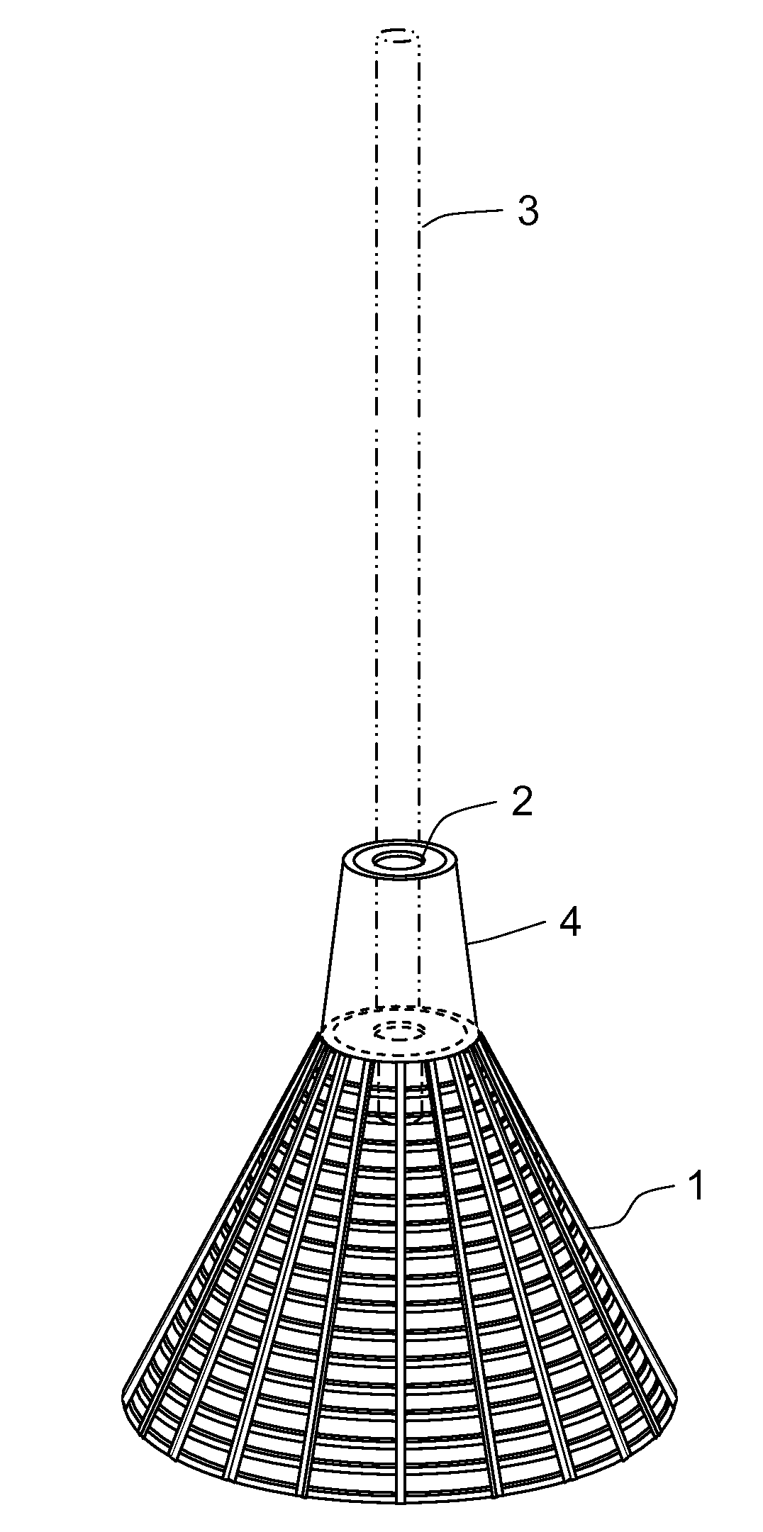
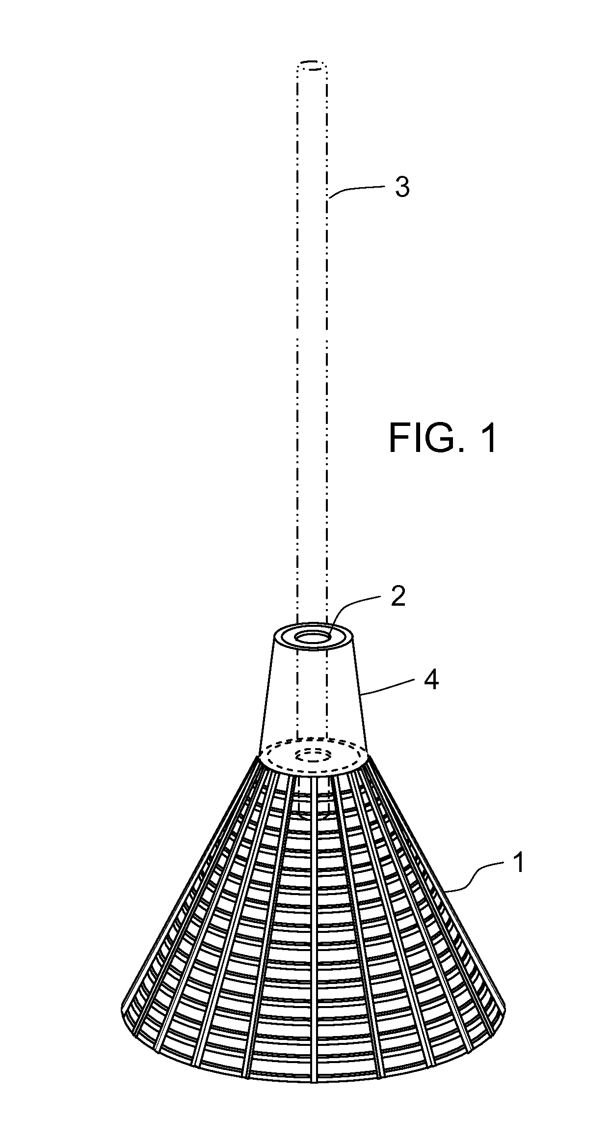
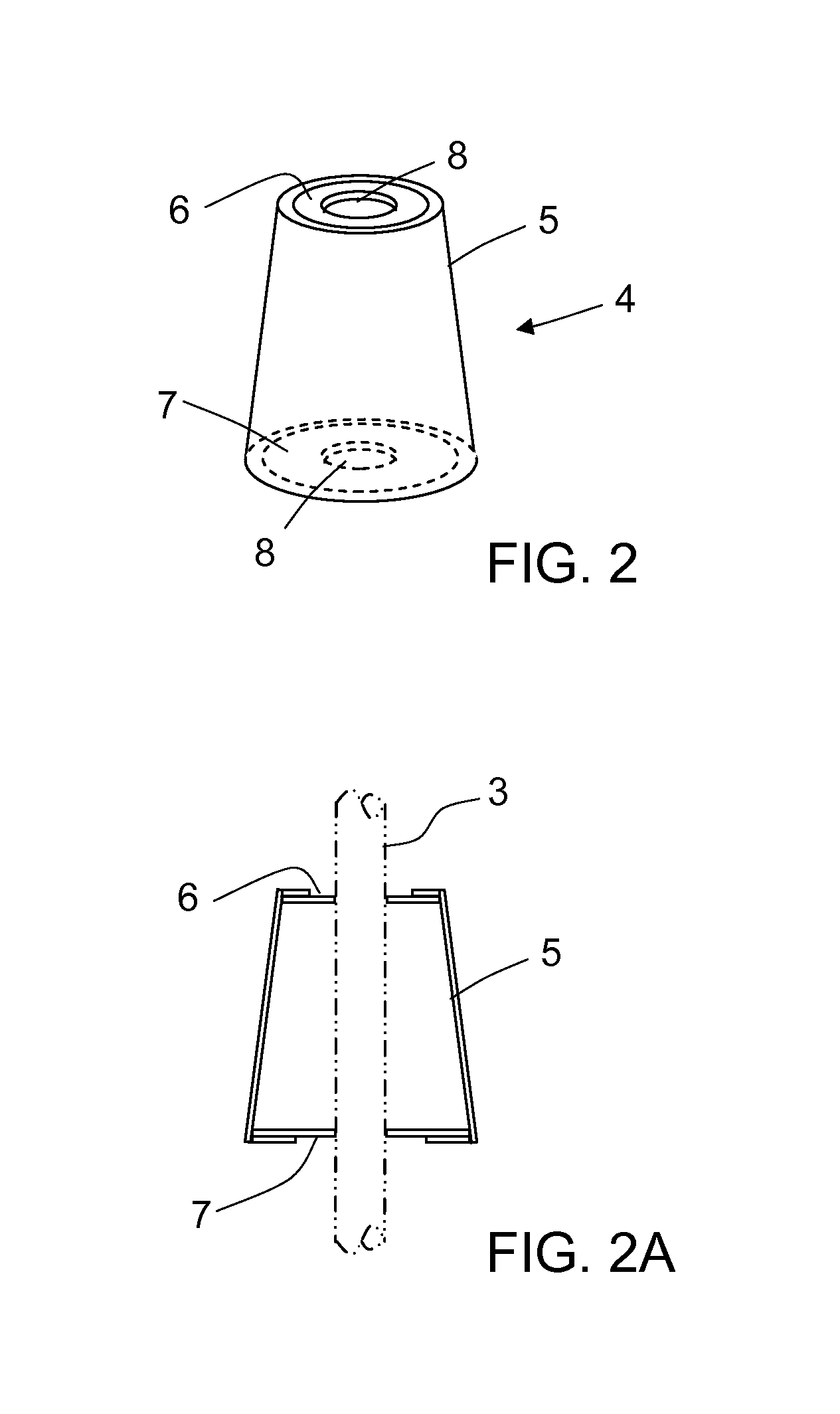
[0072]This invention is a cone structure affixed at the bottom end of a straw designed to hold down and gather ice cubes near the liquid intake of a straw for the purpose of achieving a cooler temperature of the aspirated liquid and a greater economy of ice. It comprises:[0073]a. a truncated cone made up a net, a mexh or a solid sheet and having its base at the lower end and its apex at the top end,[0074]b. the apex is traversed by a hole through which a straw can pass,[0075]c. furthermore, the apex also comprises an attachment mechanism for affixing a straw, the attachment mechanism being non-detachable from the apex;

This cone operates by directing the ice cubes toward the axis of the cone and toward the bottom opening of the straw.

[0076]An embodiment of the invention is illustrated in FIG. 1. It comprises a cone and positioned such that the base of the cone is at the bottom, and the apex of the cone is at the top. The apex is truncated to include a hole 2 large enough to allow a s...


PUM

PropertyMeasurementUnit
flexibleaaaaaaaaaa
forceaaaaaaaaaa
outer diameteraaaaaaaaaa

Abstract

This invention improves the cooling effect of ice in a drinking cup and economizes on the amount of ice used. The invention comprises a truncated cone with the widest base at the bottom, and with a hole at its apex, the hole being large enough to allow a straw to pass through. It also comprises a mechanism located at the apex of the cone, which holds the straw in place. This cone structure prevents ice cubes, which are normally buoyant, from floating up to the surface of the liquid. Instead, the cone forces the ice to congregate near the straw inlet thereby cooling the liquid entering the straw.

Description

FIELD OF THE INVENTION[0001]The present invention relates to drinking cups and glasses containing iced beverages and more particularly to devices that can be mounted on a conventional drinking straw.INCORPORATION BY REFERENCE[0002]U.S. Pat. No. 7,909,176 by Merino and U.S. patent application Ser. No. 12 / 869,731 also by Merino are thereby incorporated by reference.BACKGROUND[0003]Adding ice to a drinking cup is very commonly performed in many fast food restaurants for the purpose of providing a cold drink to the customer. Since ice commonly floats to the surface of the drink and the straw intake located at the lower extremity of the straw is normally at the bottom of the cup, the liquid at the bottom near the straw intake is not as cold as it could be. One solution is to use a large amount of ice in proportion to the liquid in the cup. This approach has the unfortunate result of diluting the drink when the ice melts and of wasting ice. Existing art also has the disadvantage of keepin...

Claims


Application Information

Patent Timeline
Patent Type & Authority Applications(United States)
IPC IPC(8): A47G21/18B26D7/01
CPCA47G21/181A47G19/2211Y10T83/0448
Inventor MERINO, JAIME ANGEL
Owner MERINO JAIME ANGEL
Why Eureka
Try Eureka