Wheelchair back mounting assembly

a backrest and mounting assembly technology, applied in the field of mounting assemblies, can solve the problems of complex backrests and mounting assemblies, insufficient or appropriate support of original back supports, and inconvenient positioning, and achieve the effects of simple structure, simple structure, and less loose parts

Inactive Publication Date: 2012-12-27
ROHO
View PDF13 Cites 14 Cited by
  • Summary
  • Abstract
  • Description
  • Claims
  • Application Information

AI Technical Summary

Benefits of technology

[0011]A further aspect of the invention provides a ramp or camming surface on the latch that allows the latch to move to an open position when it is urged against the support posts and then rotate into a closed position around the post under its own weight to allow for simple, single handed attachment between the wheelchair canes.
[0012]In another aspect, a mounting clamp which is secured to the wheelchair canes and from which the support post extends is provided that is simple in construction, has fewer loose parts, that provides at least one support point, and that can be easily disassembled and adjusted to accommodate canes of various diameters with or without the use of a tool. The mounting clamp includes a mounting clamp block and an associated C-shaped band that is positioned around the wheelchair cane. The band has a first arm and a second a

Problems solved by technology

In many cases the original back support does not provide sufficient or appropriate support, or is not positioned in between the wheel chair posts, to meet the seated user's specific physical needs or tastes.
Known back rests and mounting assemblies for back rests are complex and do not always allow for simple adjustment of the back rest, for example, without a tool.
They generally include a back and do not provide for a mounting assembly that can be used to mount different back supports between the wheel chair canes.
A

Method used


Image

  • Wheelchair back mounting assembly
  • Wheelchair back mounting assembly
  • Wheelchair back mounting assembly

Examples


Embodiment Construction

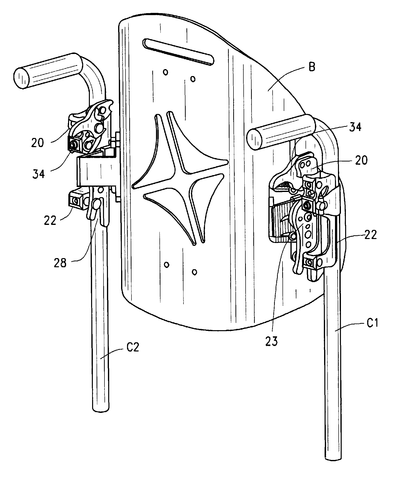
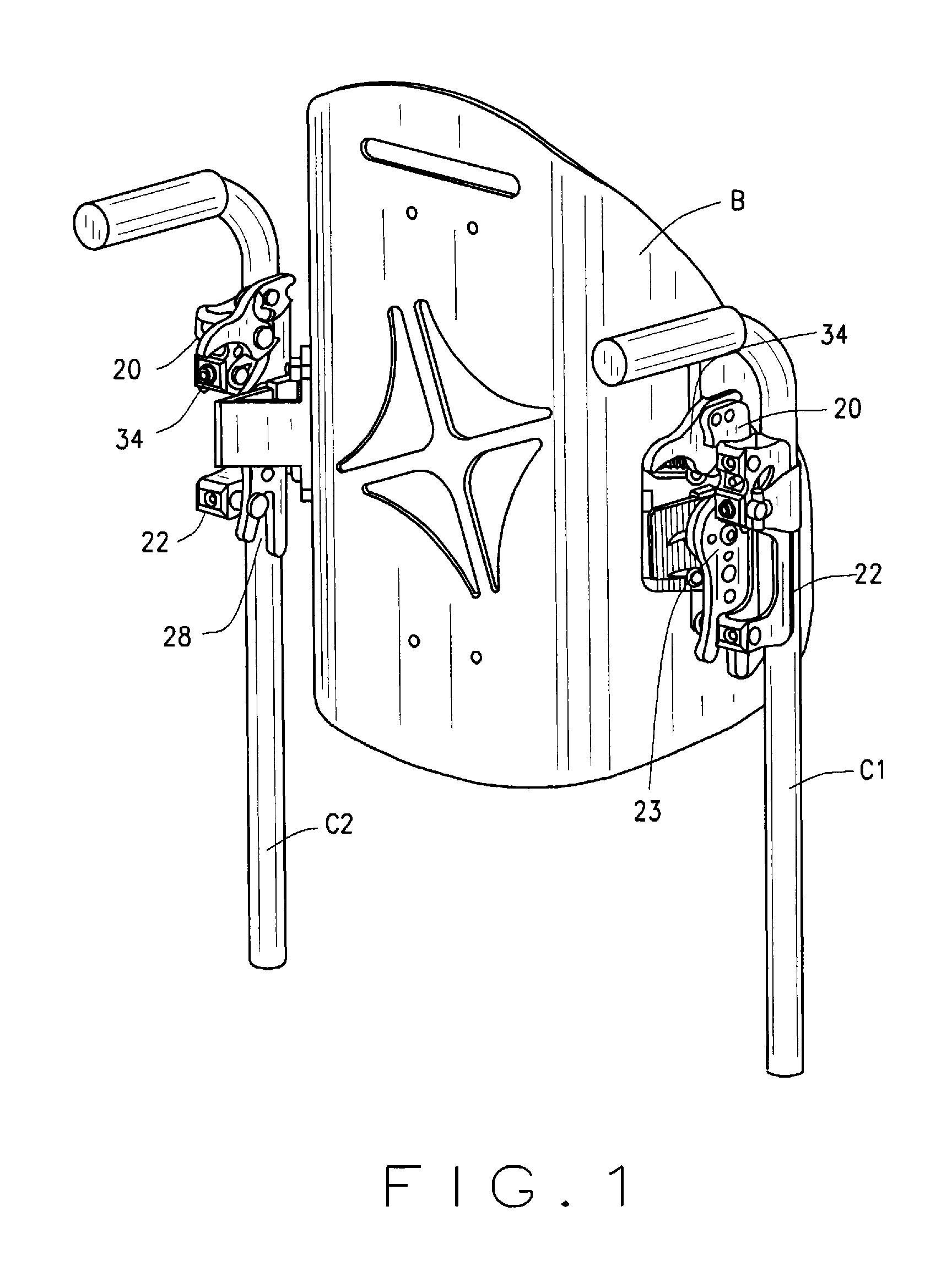
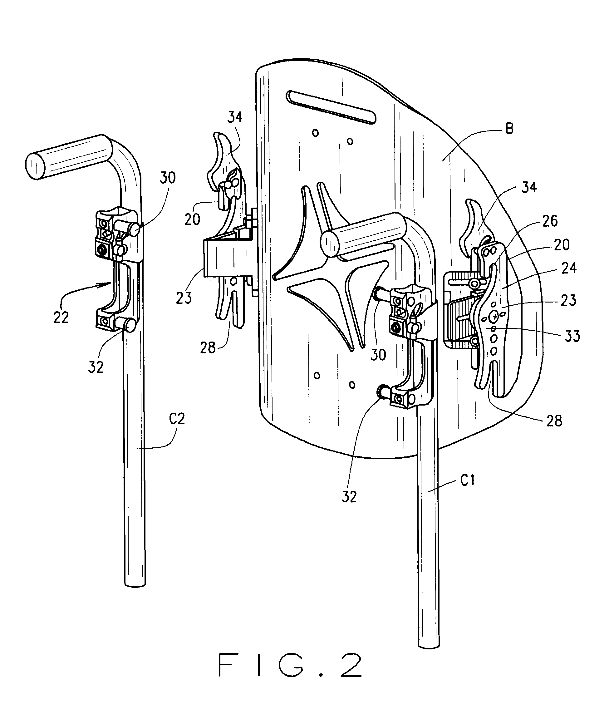
[0035]The wheelchair mounting assembly and one embodiment of the clamp and mounting post assembly of the present invention are indicated by reference numerals 20 and 22 respectively in FIGS. 1 and 2. A mounting assembly 20 is attached to each side of a wheelchair back B. Wheelchair back B is positioned between wheelchair canes C1 and C2. It will be appreciated from FIG. 1 that one object of the wheelchair mounting assembly 20 is to provide means for mounting a wheelchair back B to the canes C1 and C2. It will be noted that the mounting assemblies 20 on each side of the wheelchair back B are mirror images. The wheelchair back B can be of any acceptable construction and can employ a rigid back or shell and a pad or cushion on the front side to provide a comfortable resting area for a user of the wheelchair.

[0036]As an initial matter, mounting assembly 20 includes an adjustment apparatus, indicated generally by reference number 23. Adjustment apparatus 23 allows for varying the positio...


PUM


Abstract

A support mechanism (20) for mounting a wheelchair back to a wheelchair post including at least one generally horizontally extending support pin (30), the support mechanism (20) comprising a hanger arm (24) having a downwardly opening hook (26) defining an upper support point and a self-locking latch (34) pivotally mounting to the hanger arm (24), the latch defining a locking notch (40) and a stop notch (42), the latch (34) being pivotal between a locked position in which the latch locking notch (40) and the hook (26) define a substantially closed hole around the support pin (30) and an unlocked position in which the pin (30) is seated in the stop notch (42) such that the latch (34) is secured open so the hanger arm hook (26) can be connected to or removed from the wheelchair post support pin (30); the latch (34) is shaped and weighted such that the latch can be moved to the locked position under the force of gravity.

Description

CROSS REFERENCE TO RELATED APPLICATIONS[0001]This application claims the benefit of U.S. provisional application Ser. No. 61 / 303,471, filed Feb. 11, 2010 and PCT / US2009 / 052677, filed Aug. 4, 2009, which claims the benefit of U.S. provisional application Ser. No. 61 / 086,994 filed Aug. 7, 2008 and Ser. No. 61 / 097,574 filed Sep. 17, 2008, all of which are incorporated herein in their entirety by reference.BACKGROUND OF THE INVENTION[0002]The disclosure relates generally to mounting assemblies to secure wheelchair back supports to the canes of wheelchairs. In one aspect, the mounting includes a gravity-driven latch for attaching the mounting assembly to a support point or support post on the wheel chair canes. In a further aspect, the mounting assembly includes a mounting clamp support assemblies from which the support post extends.[0003]Wheelchairs generally comprise a frame with surface engaging wheels, a seating surface and a back support. The frame usually is made from tubular steel...

Claims


Application Information

Patent Timeline
IPC IPC(8): A47C7/42
CPCA61G5/1067A61G2203/78A61G2005/122A61G5/12A61G5/122Y10S297/04Y10T403/30Y10T403/7111
Inventor GOECKEL, GREGORY W.
Owner ROHO
Why Eureka
Try Eureka