System and method for image calibration

a technology of image calibration and system, applied in the field of vision systems, can solve the problems of insufficient measurement size, insufficient calibration target alone, and inability to measure or prepare a vision system, and achieve the effect of reducing the number of calibration targets

Inactive Publication Date: 2012-12-27
HNJ SOLUTIONS
View PDF22 Cites 21 Cited by
  • Summary
  • Abstract
  • Description
  • Claims
  • Application Information

AI Technical Summary

Benefits of technology

[0010]An object of the present invention is to provide a durable, industrial class calibration card which can be reused to calibrate product-specific manufacturing vision systems.
[0012]An object of the present invention is to provide an easy method to calibrate size in the real world based on known size markings, and to calibrate a product image without moving the calibration card or changing the focal point.

Problems solved by technology

However, configuring the machine vision system can be difficult when a particular product requires customized vision system applications to be developed to inspect for specific defects in a product during mass manufacturing on an automated basis.
Dots alone, or a checkerboard alone, are insufficient to calibrate measurement size simultaneously with the target size of a vision system application, such as a product or component which is to be verified for correct dimensions.
Further, calibration targets alone do not provide a way to measure or prepare a vision system solution for multiple deployments or for remote diagnosis.
Conventional glass calibration targets suffer from problems such as reflectivity causing abnormalities in image calibration or detection, transparency, breakability, and are not a convenient size.
Transparent and reflective characteristics produce lighting problems during imaging.
Calibration targets made of paper or mylar are typically thin and do not maintain shape when laid upon a non-flat surface.

Method used


Image

  • System and method for image calibration
  • System and method for image calibration
  • System and method for image calibration

Examples


Embodiment Construction

[0023]In the following description of the preferred embodiments, reference is made to the accompanying drawings that form a part hereof, and in which is shown by way of illustration specific embodiments in which the invention may be practiced. It is to be understood that other embodiments may be utilized and structural changes may be made without departing from the scope of the present invention.

[0024]References throughout the specification to “a possible embodiment,”“a preferred embodiment,”“some embodiments,”“an embodiment,” and like reference to “embodiment” are non-limiting examples to aid in understanding an element, function, way, result, means, structure, aspect, and / or benefit of the present invention. An “embodiment” provides that there is one or more embodiments that can involve the given element or aspect of the invention. Thus, multiple instances of “an embodiment” and like reference do not necessarily refer to the same embodiment.

[0025]References to the following shall ...


PUM


Abstract

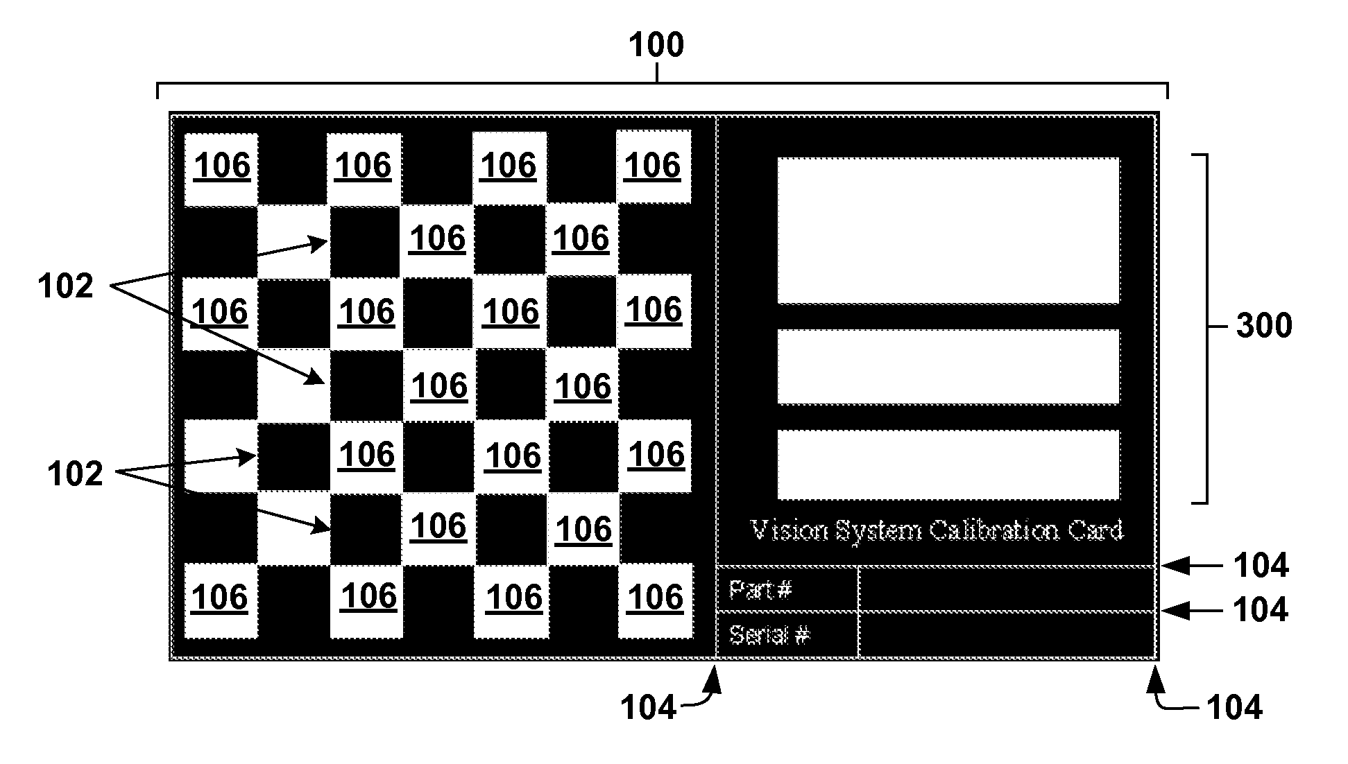
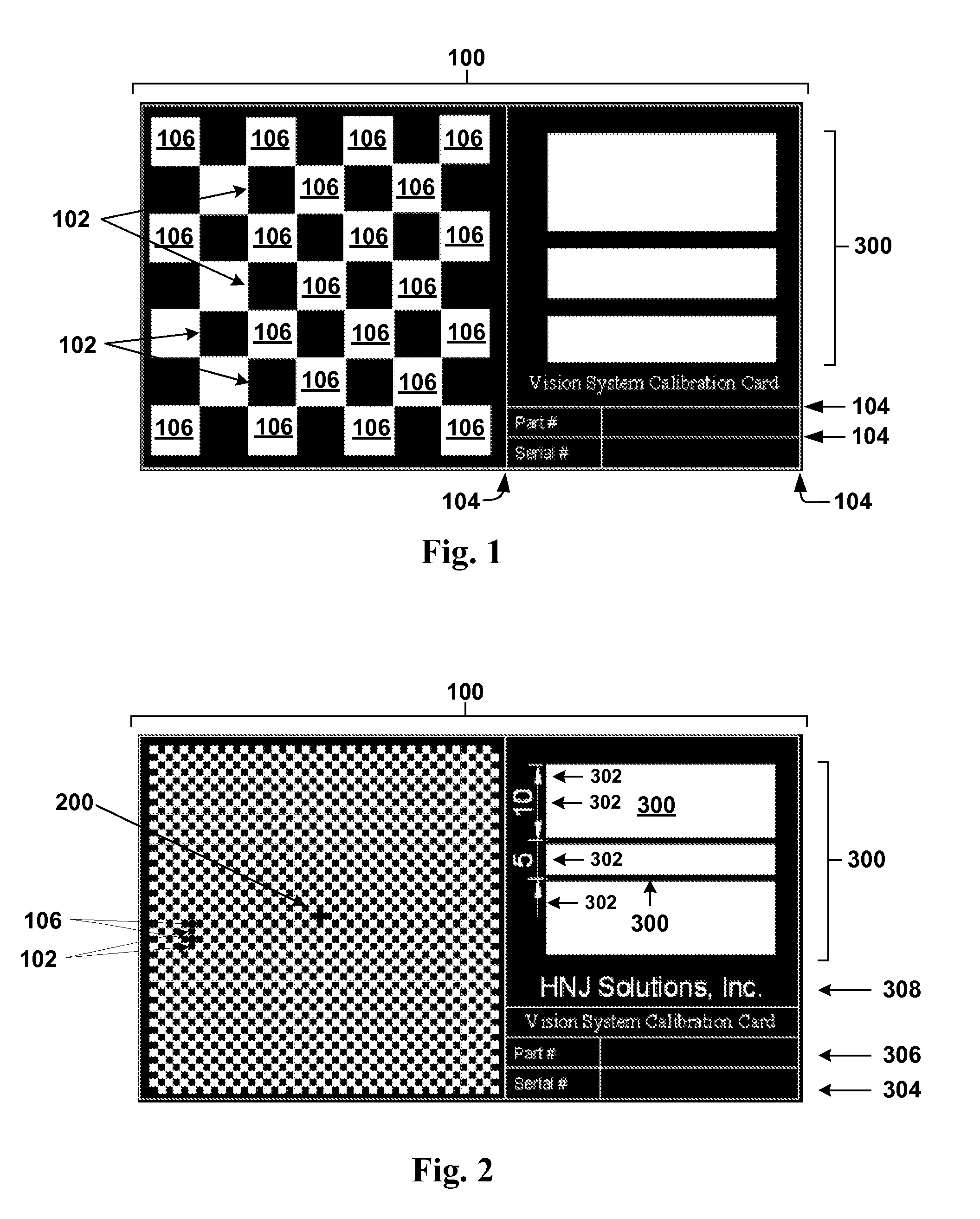
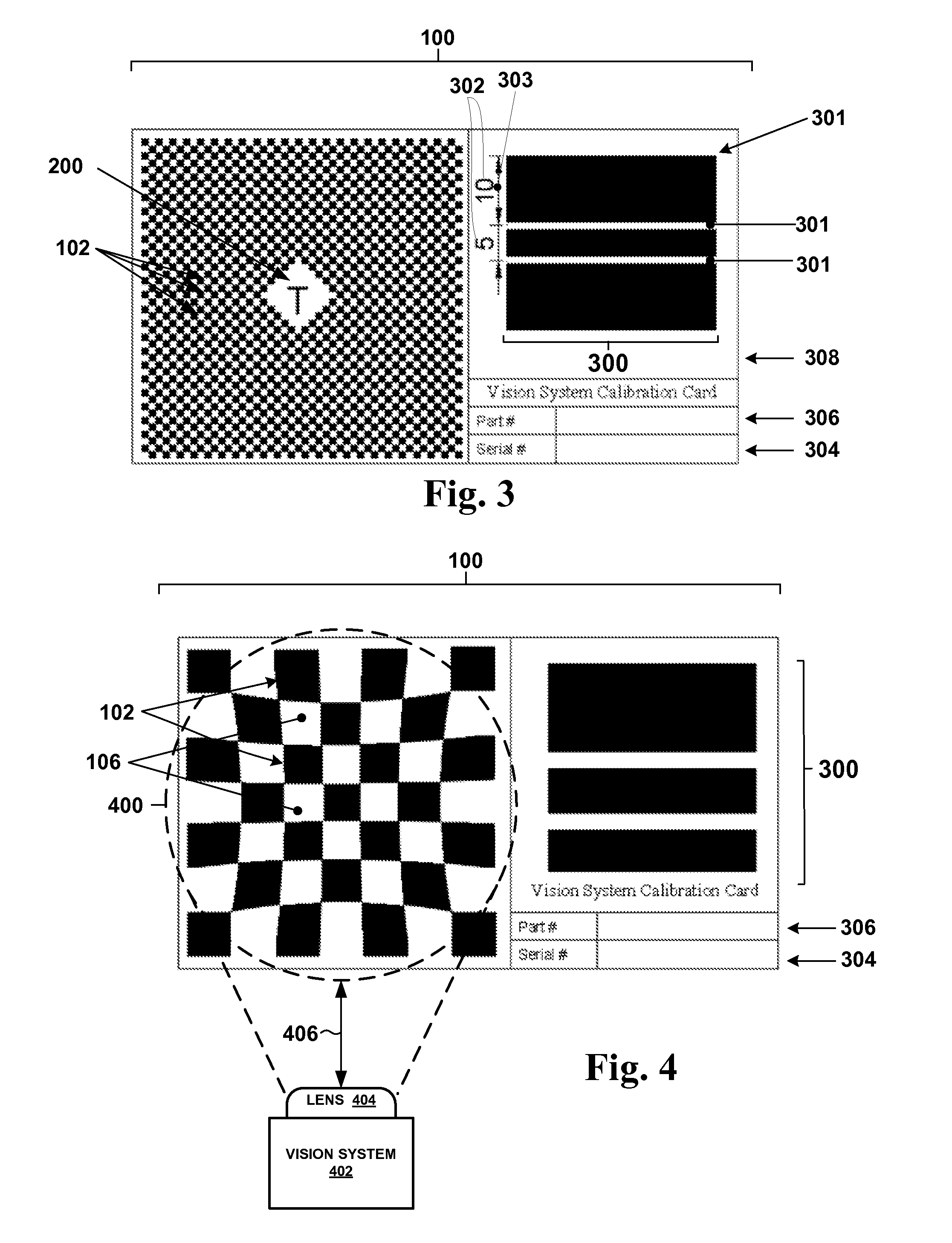
The present invention discloses a system for smart camera image calibration, comprising a calibration card, a size marking on the calibration card, and a calibration image on the calibration card. A method for smart camera image calibration comprises calibrating a vision system to a size marking, capturing a calibration verification image, and verifying the calibration verification image based on the size marking. A smart camera calibration system comprises a vision system, a first calibration parameter programmed into the vision system, a calibration card comprising a size marking, and a calibration image, wherein the calibration image is shown on the calibration card and in the vision system, wherein the calibration image substantially corresponds to at least some portion of a product, and wherein the size marking does not bear similarity to the at least some portion of the product.

Description

BACKGROUND OF THE INVENTION[0001]1. Field of Invention[0002]This invention relates to vision systems, in particular, to machine vision image calibration cards for inspection of products in automated mass manufacturing applications.[0003]2. Description of the Related Art[0004]Machine vision systems, including smart cameras, are known in the related art. Some vendors include: Keyence, Cognex, DVT (which was acquired by Cognex), Matrox, and Omron, among others. Machine vision systems are often used to inspect products for defects in mass manufacturing industrial environments. However, configuring the machine vision system can be difficult when a particular product requires customized vision system applications to be developed to inspect for specific defects in a product during mass manufacturing on an automated basis.[0005]Calibration targets are also known in the related art. Many conventional calibration targets often have only dots or a checkerboard pattern. Dots alone, or a checker...

Claims


Application Information

Patent Timeline
Patent Type & Authority Applications(United States)
IPC IPC(8): H04N17/00H04N7/18
CPCH04N17/002G01N21/93
Inventor MCENTYRE, GREGORY J.
Owner HNJ SOLUTIONS
Why Eureka
Try Eureka