

Lens barrel and camera body
a technology of lens barrel and camera body, which is applied in the direction of camera focusing arrangement, printers, instruments, etc., can solve the problem of not being able to capture an image focused on the object, and achieve the effect of well-captured images
- Summary
- Abstract
- Description
- Claims
- Application Information
AI Technical Summary
Benefits of technology
Problems solved by technology
Method used
Image

Examples
first embodiment
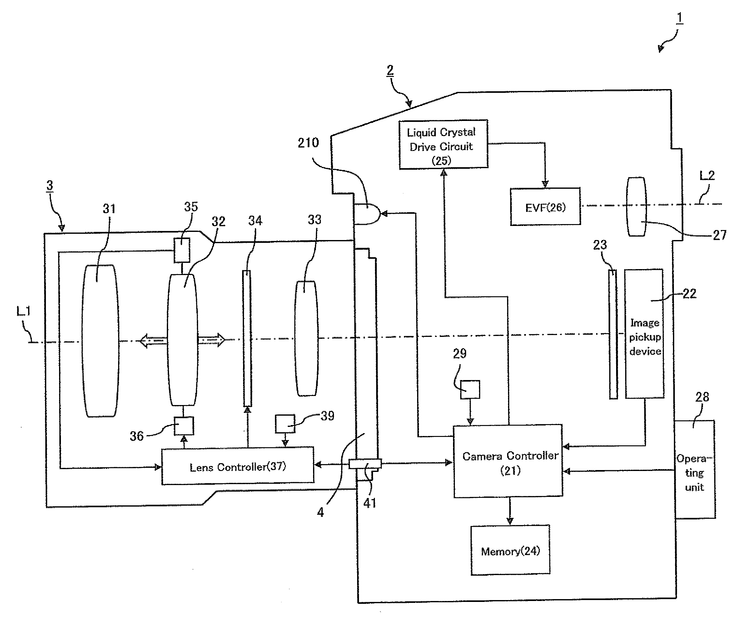
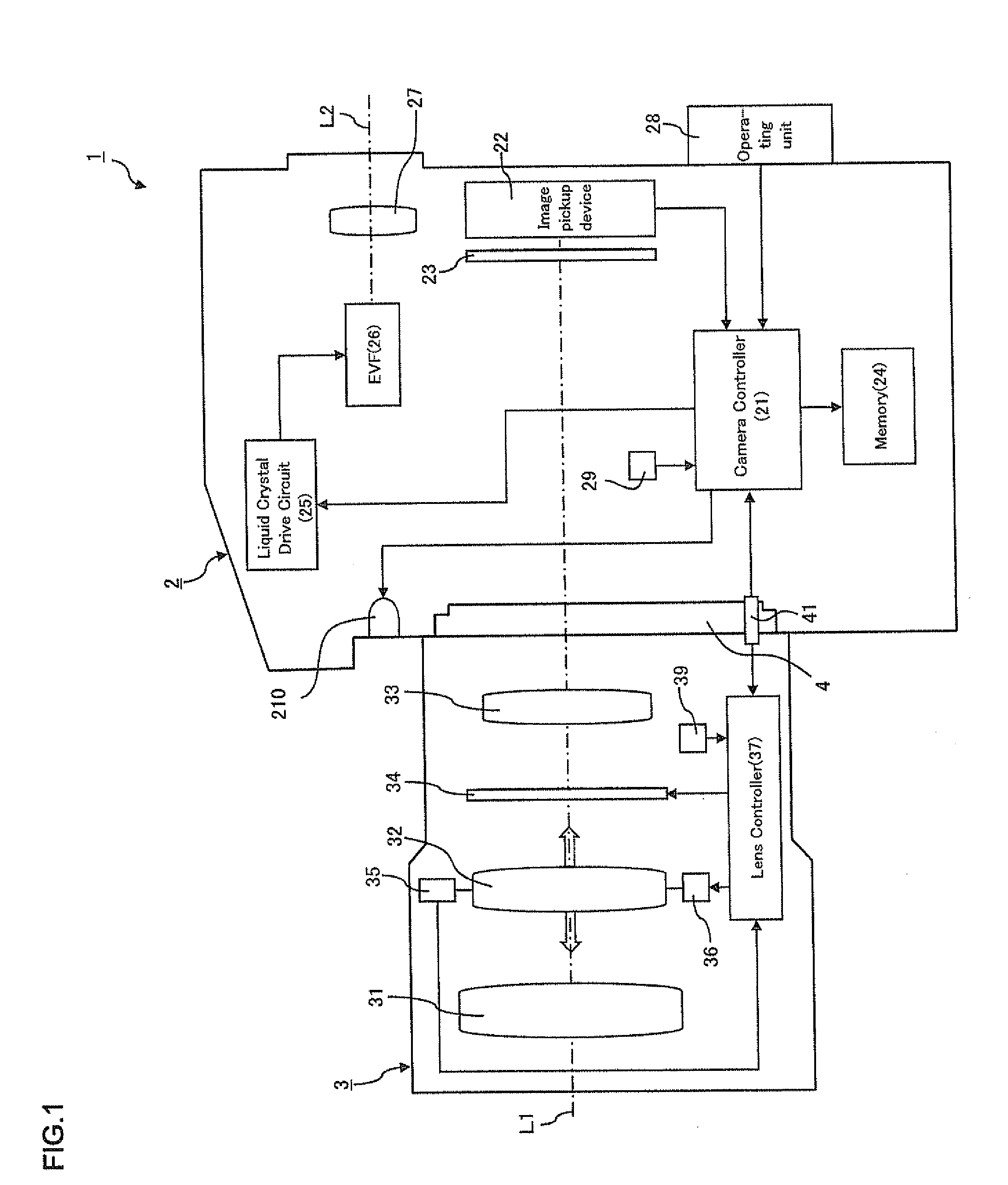
[0090]FIG. 1 is a view of the configuration of principal parts which shows a digital camera 1 according to an embodiment of the present invention. The digital camera 1 of the present embodiment (below, simply referred to as the “camera 1”) is comprised of a camera body 2 and a lens barrel 3. These camera body 2 and lens barrel 3 are detachably connected by a mount 4.
[0091]The lens barrel 3 is an exchangeable lens which can be detachably attached to the camera body 2. As shown in FIG. 1, the lens barrel 3 houses a capture optical system which includes lenses 31, 32, and 33 and an aperture 34.
[0092]The lens 32 is a focus lens which can move along the optical axis L1 direction so as to adjust the focal distance of a capture optical system. The focus lens 32 is provided to be able to move along the optical axis L1 of the lens barrel 3 and is detected in position by an encoder 35 while being adjusted in position by a focus lens drive motor 36.
[0093]The specific configuration of the movem...
second embodiment
[0165]Next, a second embodiment of the present invention will be explained based on the drawings. The camera 1a according to the second embodiment, as shown in FIG. 12, has a configuration similar to the camera 1 according to the first embodiment except for the fact that the lens barrel 3a is mounted to the camera body 2 through a lens adapter 5 and performs a similar operation to the camera 1 according to the first embodiment except for the points explained below.
[0166]That is, the camera 1a according to the second embodiment can mount the lens barrel 3a at the camera body 2 through the lens adapter 5. Here, the lens barrel 3a has a configuration similar to the lens barrel 3 of the first embodiment except for the fact that it does not store the opening side limit value in the memory 39. Further, in the second embodiment, for example, by the lens barrel 3a being mounted at the camera body 2 through the lens adapter 5, the adapter controller 51 sends the camera controller 21 and lens...
third embodiment
[0171]Next, a third embodiment of the present invention will be explained based on the drawings. In the third embodiment, in the camera 1 which is shown in FIG. 1, a similar operation is performed as in the camera 1 according to the first embodiment except for using the later explained variable amount of the aperture value as the basis to control the aperture value at the time of focus detection.
[0172]In the third embodiment, the lens controller 37, as shown in FIG. 14, stores the range of aperture values which can be set as the aperture value of the optical system at the time of focus detection in the memory 39 as the variable amount of the aperture value from the capture aperture value. Here, for the image capture after focus detection, when changing the aperture value of the optical system from, for example, the aperture value F1.4 at the time of focus detection to the capture aperture value F2 for image capture, sometimes movement of the image plane accompanying a change of the ...
PUM
 Abstract
Description
Claims
Application Information