Method and apparatus for transmitting and receiving data in broadcasting system

a broadcasting system and channel code technology, applied in the field of transmitting and receiving channel codes, can solve the problems of low decoding complexity, increase in decoding complexity, and the receiver may not restore input data from received coded data, etc., and achieve the effect of improving the performance of the receiver

Inactive Publication Date: 2012-12-27
SAMSUNG ELECTRONICS CO LTD
View PDF5 Cites 4 Cited by
  • Summary
  • Abstract
  • Description
  • Claims
  • Application Information

AI Technical Summary

Benefits of technology

[0008]The present invention has been made to address at least the above problems and / or disadvantages and to provide at least the advantages described below. Accordingly, an aspect of the present invention provides a method and apparatus for transmitting and receiving additional parity to improve performance of a receiver.

Problems solved by technology

However, since turbo codes reach their performance limits at a very low error rate, which is required in 4th generation mobile communication systems, the interest in new types of graph-based coding methods has increased.
In situations where a Signal-to-Noise Ratio (SNR) is low or an error occurs frequently, a receiver may not restore input data from received coded data.
When the additionally transmitted parity is not identical to the first transmitted coded data or any part thereof, the receiver performs decoding taking into account both the first transmitted coded data and the additionally transmitted parity, causing an increase in decoding complexity.
In addition, when the additionally transmitted parity is the same as the first transmitted coded data or any part thereof, and data is transmitted in a simple iterative manner using the same modulation symbols, the decoding complexity may be low, but performance improvement may not meet the high standards that are desired.

Method used


Image

  • Method and apparatus for transmitting and receiving data in broadcasting system
  • Method and apparatus for transmitting and receiving data in broadcasting system
  • Method and apparatus for transmitting and receiving data in broadcasting system

Examples


Embodiment Construction

[0027]Embodiments of the present invention are described in detail with reference to the accompanying drawings. The same or similar components may be designated by the same or similar reference numerals although they are illustrated in different drawings. Detailed descriptions of constructions or processes known in the art may be omitted to avoid obscuring the subject matter of the present invention.

[0028]An additional parity transmission method and apparatus for improving reception performance are described in detail below according to embodiments of the present invention.

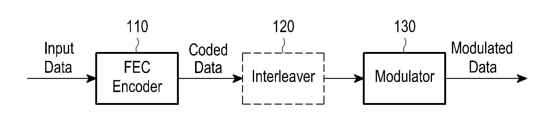
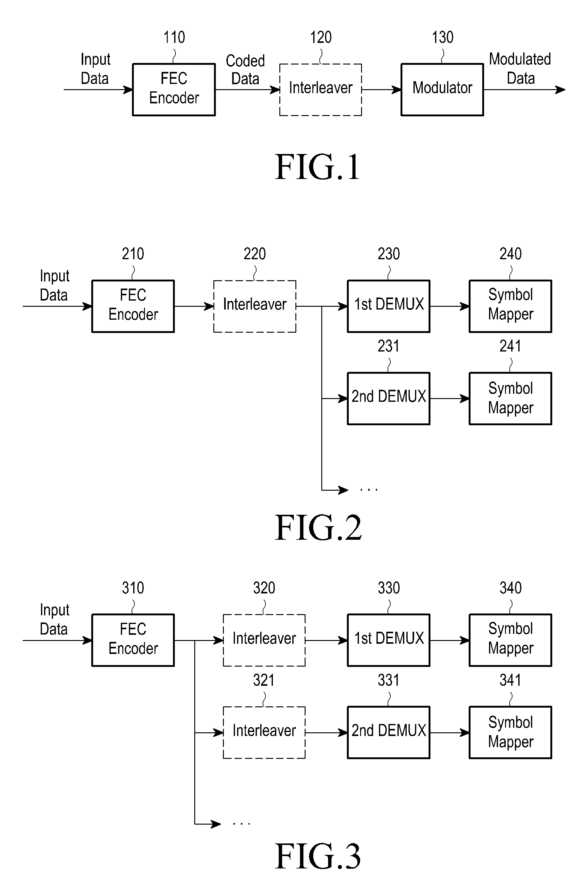
[0029]FIG. 1 is a diagram illustrating a general channel encoding and modulation process.

[0030]Referring to FIG. 1, input data to be subjected to channel encoding is input to a channel encoder 110. The channel encoder 110 encodes the input data and outputs the coded data to a modulator 130. The modulator 130 modulates the coded data into modulation symbols and transmits the modulation symbols. Optionally, an inter...


PUM


Abstract

Methods and apparatus are provided for transmitting data in a broadcasting system. Input data is encoded by an encoder. A first demultiplexer generates first transmission symbols using the encoded data. The first transmission symbols are modulated, and the modulated first transmission symbols are transmitted. A second demultiplexer generates second transmission symbols using at least a portion of the encoded data. The second transmission symbols are modulated and the modulated second transmission symbols are transmitted.

Description

PRIORITY[0001]This application claims priority under 35 U.S.C. §119(a) to a Korean Patent Application filed in the Korean Intellectual Property Office on Jun. 24, 2011 and assigned Serial No. 10-2011-0061869, the entire disclosure of which is incorporated herein by reference.BACKGROUND OF THE INVENTION[0002]1. Field of the Invention[0003]The present invention relates generally to a method for transmitting and receiving channel codes to improve performance of broadcasting and communication systems, and more particularly, to a method and apparatus for mapping generated coded data to modulation symbols, and transmitting and receiving the mapped data.[0004]2. Description of the Related Art[0005]A powerful error-correction coding technique that supports broadband data and high-speed packet transmission is a key element in next-generation mobile communication systems and broadcasting systems. Since the turbo decoding method of 1993, interest in high-performance error-correcting codes show...

Claims


Application Information

Patent Timeline
Patent Type & Authority Applications(United States)
IPC IPC(8): H04N5/40H04N5/455
CPCH04L1/0041H04L1/0045H04L1/1819H04L1/0065H04L1/0071H04L1/0057H03M13/11H03M13/27H04L27/34H04L27/36
Inventor JEONG, HONG-SILMYUNG, SE-HO
Owner SAMSUNG ELECTRONICS CO LTD
Why Eureka
Try Eureka