Image forming apparatus
- Summary
- Abstract
- Description
- Claims
- Application Information
AI Technical Summary
Benefits of technology
Problems solved by technology
Method used
Image
Examples
embodiment 1
[0021]In this embodiment, a general structure of the image forming apparatus, a mounting / demounting method of process cartridges, a structure of a transfer unit, a positioning constitution of the transfer unit and a mounting / demounting method of the transfer unit will be described in this order. Further, in this embodiment, as the image forming apparatus, a laser beam printer is described as an example. Further, as an example, the image forming apparatus in which respective color toner images (developer images) are successively transferred from photosensitive drums as an image bearing member onto a belt and then are collectively transferred from the belt onto a recording material is described.
(General Structure of Image Forming Apparatus)
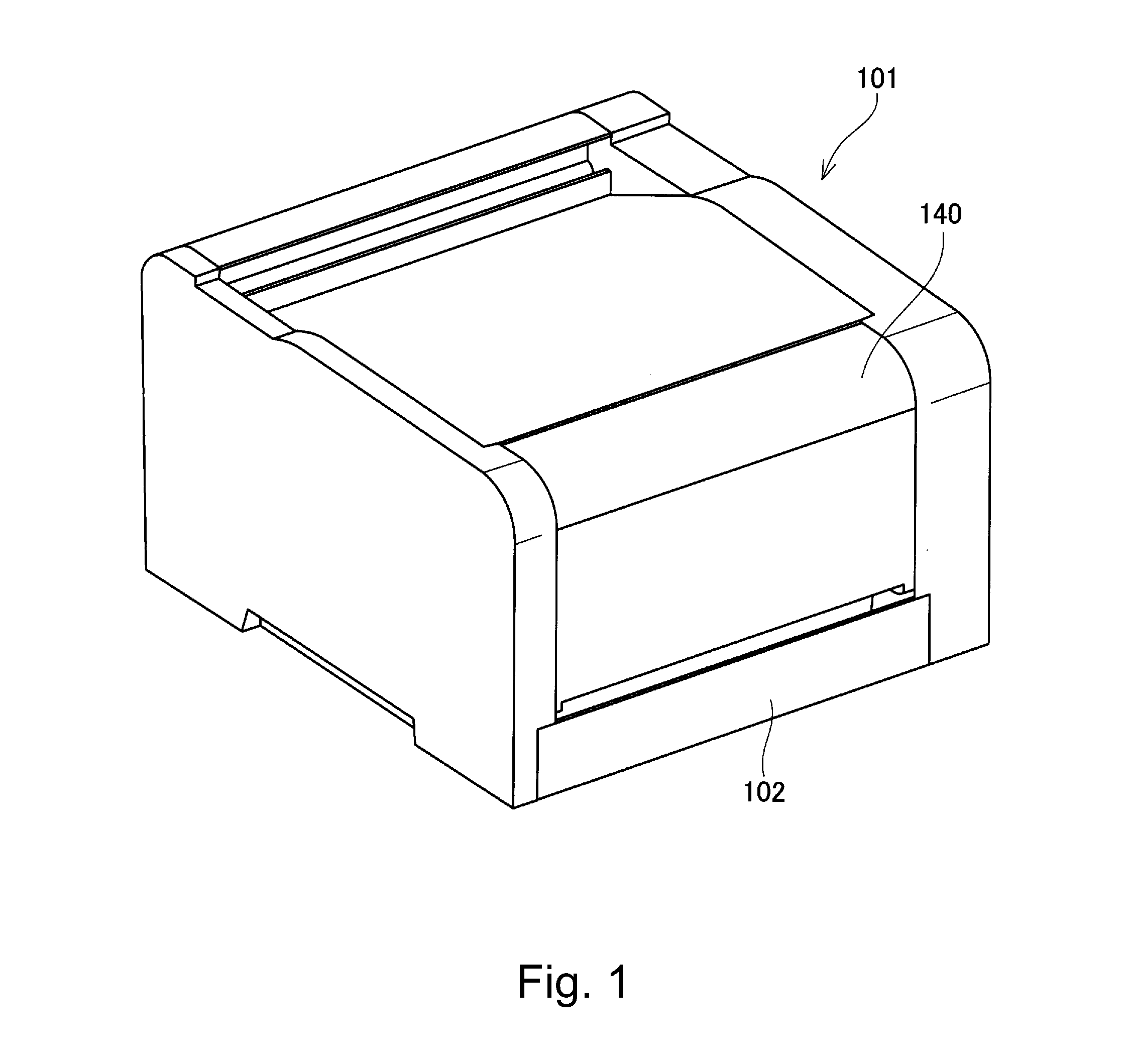
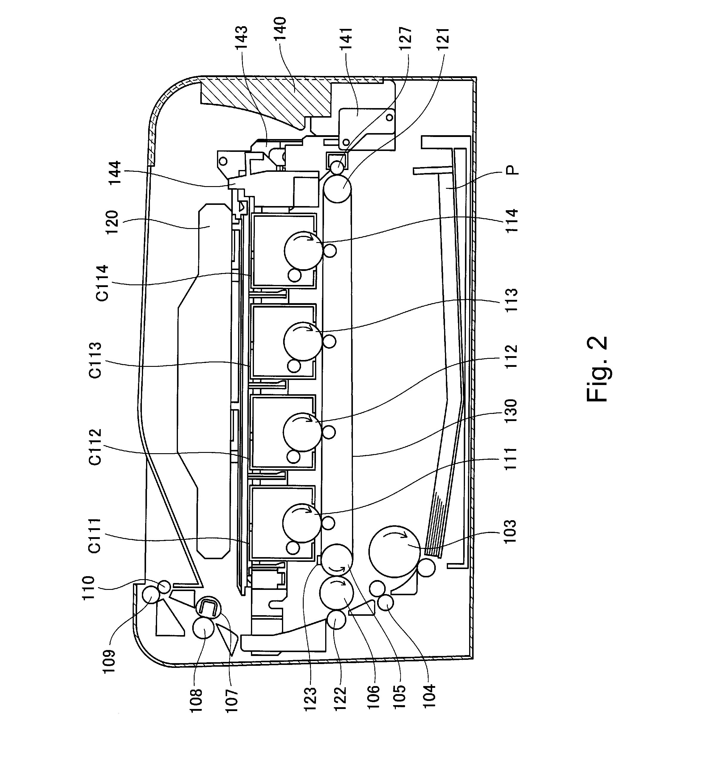
[0022]FIG. 1 is a schematic perspective view of an outer appearance of the image forming apparatus in this embodiment. FIG. 2 is a schematic sectional view of the image forming apparatus in this embodiment. A recording material P stacked and accommo...
embodiment 2
[0056]In this embodiment, the case where the second intermediary transfer member 106 is constituted so as to be detachably mountable to the transfer unit main assembly. Incidentally, constituent elements or portions similar to those in Embodiment 1 are represented by the same reference numerals or symbols and will be omitted from description.
(Structure of Transfer Unit)
[0057]The structure of the transfer unit 125 will be described with reference to FIG. 8. FIG. 8 is a schematic perspective view showing a relationship between the transfer unit 125 and a positioning portion of the apparatus main assembly 101
[0058]To a transfer frame 224 for holding the tension roller 121, during assembling of the transfer unit 125, the second intermediary transfer member 106 and the inner belt driving roller 105 are positionally fixed by a positioning tool (not shown) at their bearing portions. Here, the transfer unit 224 corresponds to the transfer unit transfer frame 224 corresponds to the transfer ...
embodiment 3
[0067]This embodiment is characterized by the mounting / demounting method of the transfer unit. In a state in which the process cartridges and mounted in the apparatus main assembly 101, the transfer unit 125 is constituted so as to be detachably mountable to the apparatus main assembly. Incidentally, constituent elements or portions similar to those in Embodiments 1 and 2 are represented by the same reference numerals or symbols and will be omitted from description.
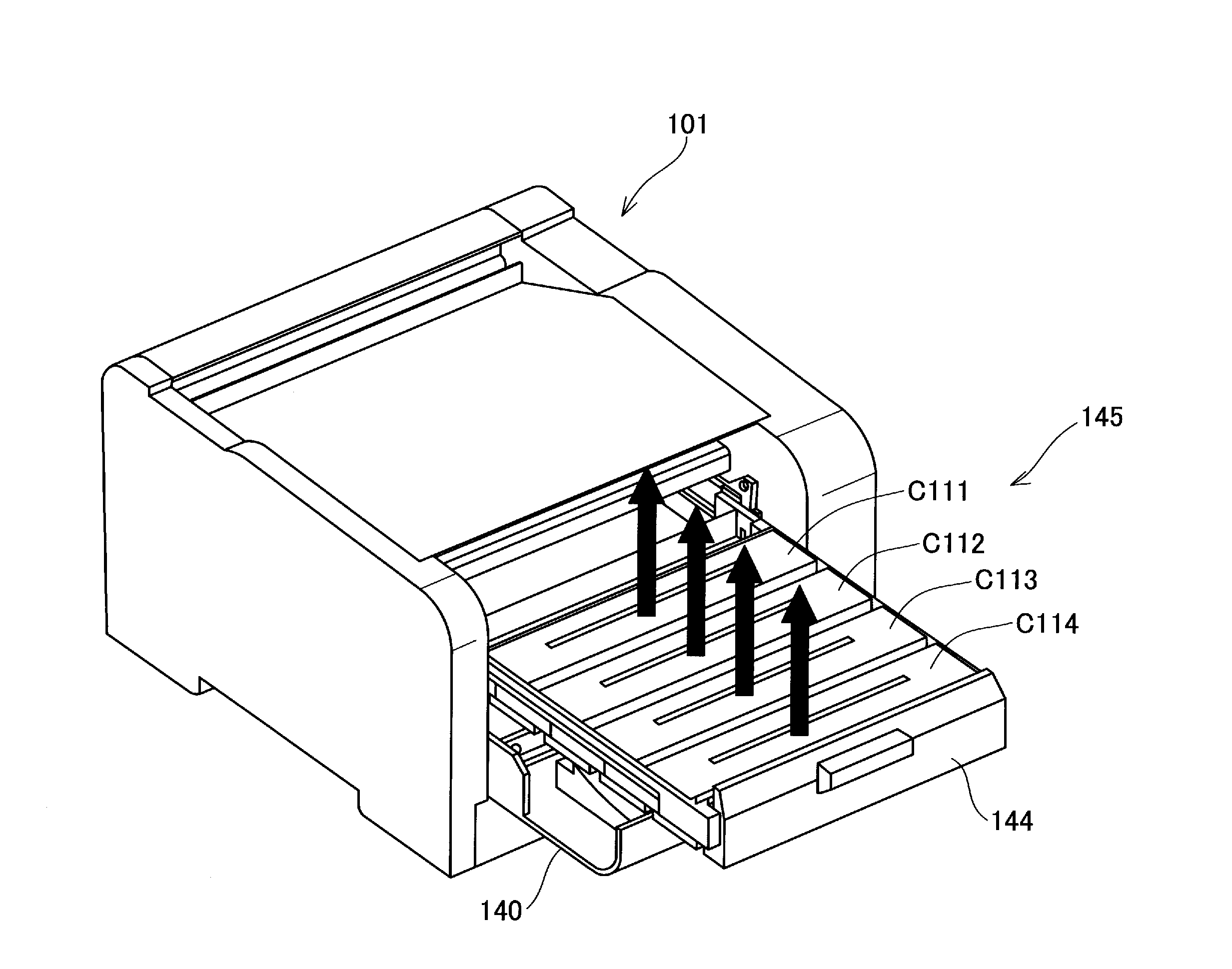
[0068]The mounting / demounting method of the transfer unit 125 will be described with reference to FIGS. 8, 9 and 10. FIG. 9 is a schematic sectional vie of the image forming apparatus for illustrating the mounting / demounting method of the transfer unit.
[0069]FIG. 10 is a schematic perspective vie of the image forming apparatus for illustrating the mounting / demounting.
(Mounting / Demounting Method of Transfer Unit)
[0070]The replacement of the transfer unit 125 is, in order to improve usability, of the front-access replacemen...
PUM
 Abstract
Description
Claims
Application Information
 - R&D
- Intellectual Property
- Life Sciences
- Materials
- Tech Scout
- Unparalleled Data Quality
- Higher Quality Content
- 60% Fewer Hallucinations
Browse by: Latest US Patents, China's latest patents, Technical Efficacy Thesaurus, Application Domain, Technology Topic, Popular Technical Reports.
© 2025 PatSnap. All rights reserved.Legal|Privacy policy|Modern Slavery Act Transparency Statement|Sitemap|About US| Contact US: help@patsnap.com


