
Roll formed steel beam

a technology of steel beams and rolled beams, applied in the field of cold rolled ibeams, can solve the problems of high manufacturing cost of hot rolled beams used today, high cost of aluminum, and high cost of beams

Active Publication Date: 2012-12-27
ISPAN SYST LP
View PDF29 Cites 21 Cited by
  • Summary
  • Abstract
  • Description
  • Claims
  • Application Information

AI Technical Summary

Benefits of technology

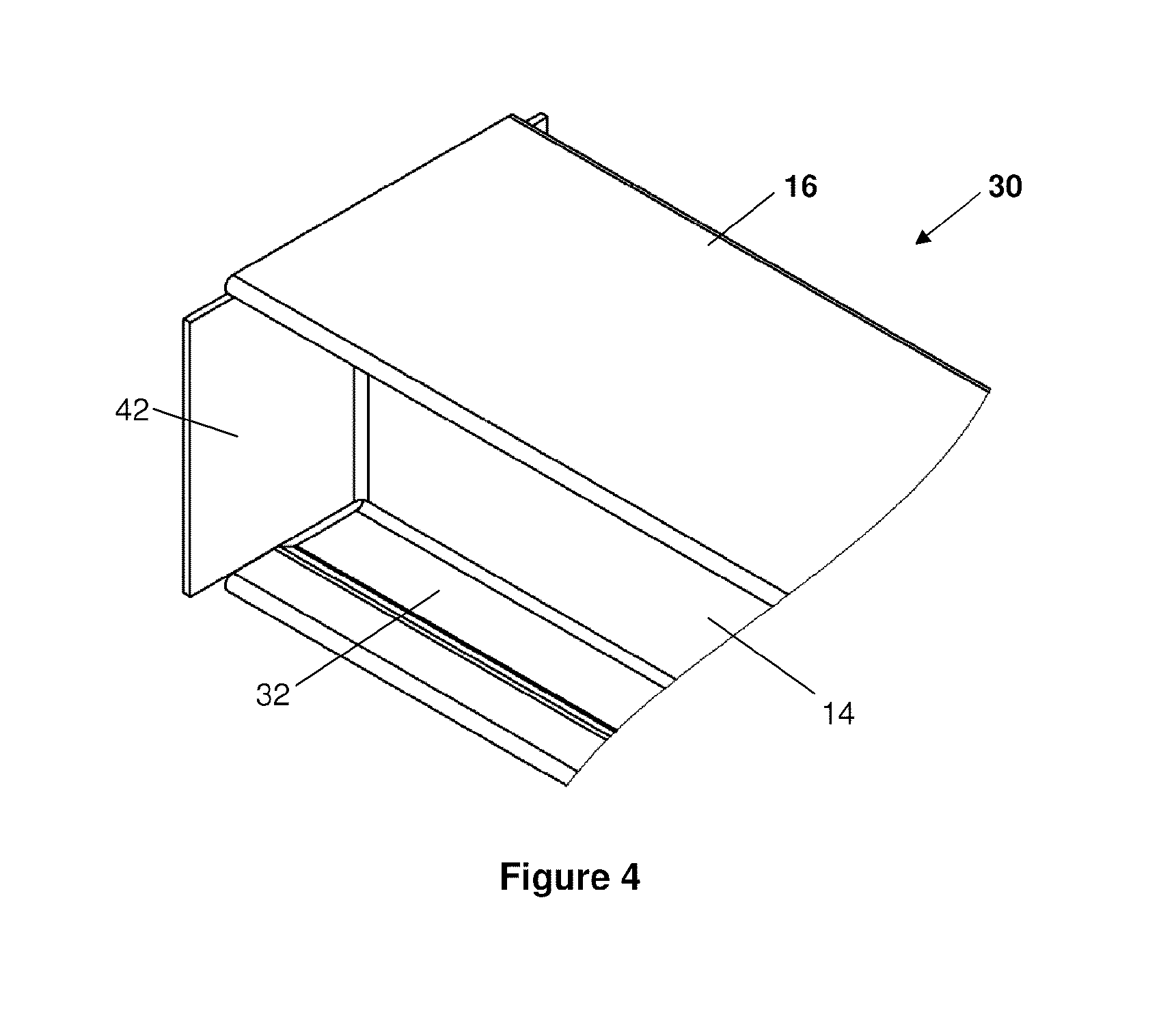
[0017]In a further embodiment of the present invention, said cut steel material has an end connector at each end thereof, and the method further includes the step of: punching each end connector by folding each end connector so that each end connector is positioned generally orthogonally to the web and top and bottom flanges at each end of the cold rolled steel beam.
[0018]Preferably, the method includes the step of punching stiffeners between each end connector and the web. Even more preferably, the cold rolled steel beam includes a pair of bottom flanges extending outwardly from the bottom end of the web; and a pair of top flanges extending outwardly from the top end of the web; each top flange having two layers of steel; and each top flange having two layers of steel.

Problems solved by technology

After fabrication a finish is applied to the beams since they may be exposed to difficult weathering conditions.
The hot rolled beams used today are typically expensive to manufacture because there is not a lot of weight in the each section.
However, aluminum is very expensive, thus these beams are expensive to produce.
The shape in itself is very efficient structurally, but when customizing small members with connections and providing protective coating the costs per unit weight become very expensive.

Method used


Image

  • Roll formed steel beam
  • Roll formed steel beam
  • Roll formed steel beam

Examples


Embodiment Construction

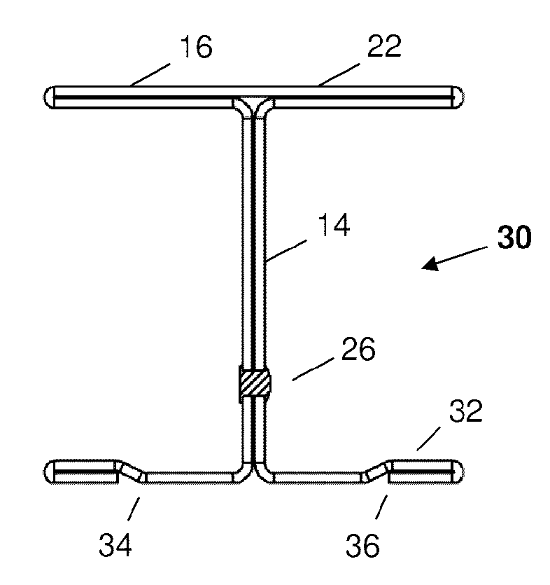
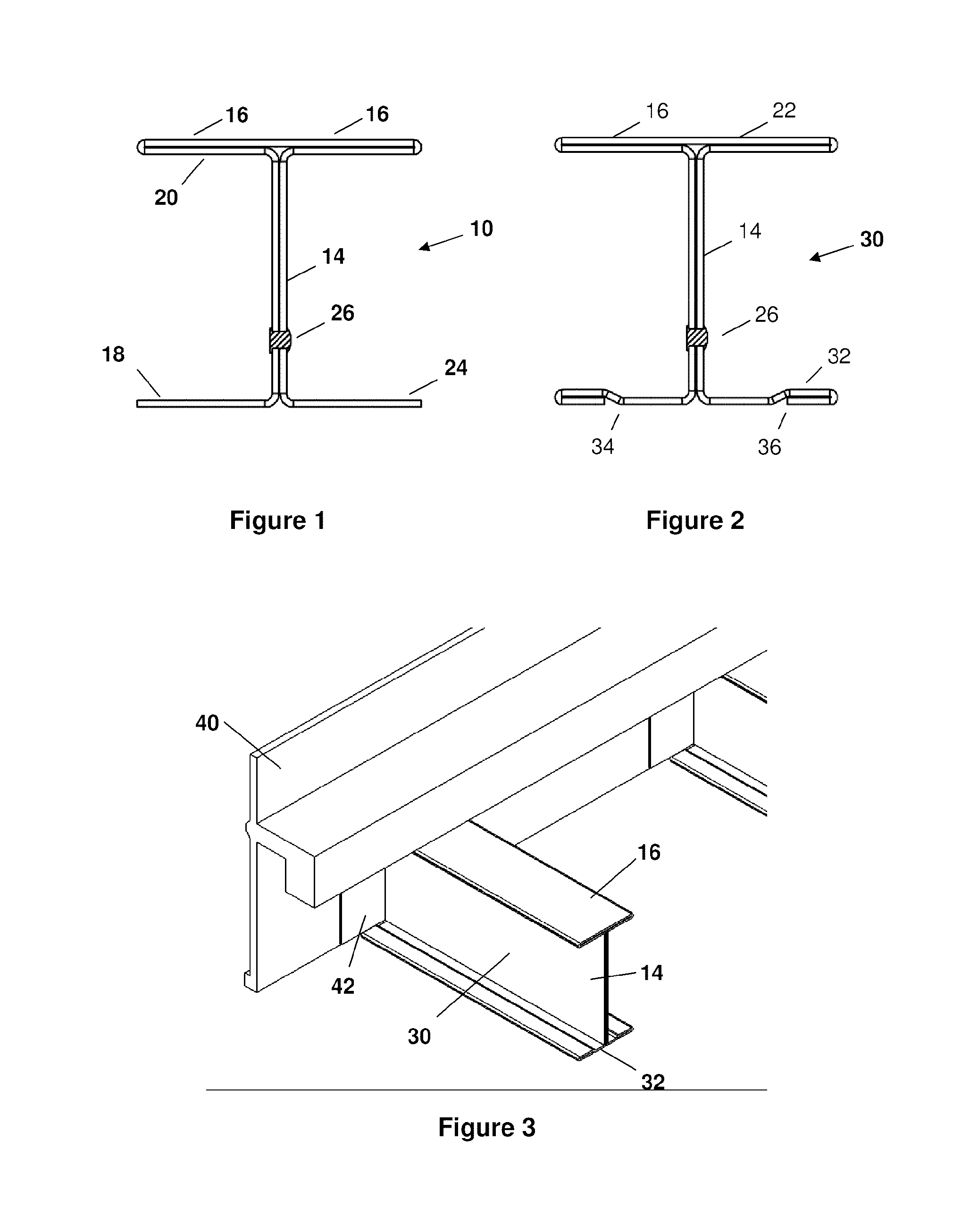
[0044]Referring to FIG. 1, a steel I-Beam is made by cold forming beams from coil material and is shown generally at 10. Beam 10 is a cold rolled steel beam including a bottom pair of bottom flanges 12, a web 14 and a pair of top flanges 16. The web 14 has a double thickness of steel and the top flanges 16 have a double thickness of steel. The beam 10 is constructed from a unitary piece of coil material. The cross section of the steel starts 18 at one side of the bottom flange 12 makes a generally 90 degree turn to form ones side of the web 14. It makes another generally 90 degree turn to form one side of a bottom portion 20 of the top flange 16. It makes a generally 180 degree fold to form the top portion 22 of the top flange 16 and then makes another generally 180 degree fold to form the other side of the bottom portion of the top flange 16. It then makes a generally 90 degree turn to form the other side of the web 14 and then a generally 90 degree turn to form the other side of t...


PUM

PropertyMeasurementUnit
angleaaaaaaaaaa
lengthaaaaaaaaaa
thicknessaaaaaaaaaa

Abstract

The present invention relates to a cold rolled steel beam comprising: a web having two layers of steel, the web having a top end and a bottom end; a pair of bottom flanges extending outwardly from the bottom end of the web; and a pair of top flanges extending outwardly from the top end of the web, each top flange having two layers of steel. Preferably, a portion of each bottom flange has two layers of steel, and the cold rolled steel beam includes a pair of end connectors extending generally orthogonally from the web and positioned generally orthogonally to the bottom flanges and the top flanges. Preferably, the cold rolled steel beam is cold formed from a unitary piece of sheet steel.

Description

FIELD OF THE INVENTION[0001]This invention relates to beams and in particular cold rolled I-beams made from a unitary piece of coil material. The beams are particularly useful for light structural member applications wherein I, W and S shape members are traditionally used. This new art is especially applicable to, but not limited to trailer beams, formwork beams and structural framing members.BACKGROUND OF THE INVENTION[0002]In the past trailers for commercial use that are hauled by heavy trucks have been built with numerous small I-Shape beams. These beams are hot rolled to very tight section and thickness tolerances. These beams comprise a significant part of the weight of a trailer bed. Typically these trailer beams have a plate welded at the end. After fabrication a finish is applied to the beams since they may be exposed to difficult weathering conditions. The hot rolled beams used today are typically expensive to manufacture because there is not a lot of weight in the each sec...

Claims


Application Information

Patent Timeline
Patent Type & Authority Applications(United States)
IPC IPC(8): E04C3/07B32B15/18B21H7/00B32B15/01
CPCB62D21/02B62D21/20E04C3/07E04C2003/0421Y10T29/49634E04C2003/0452Y10T428/12354Y10T428/12347E04C2003/0434
Inventor STRICKLAND, MICHAEL R.FOX, DOUGLAS M.STRICKLAND, RICHARD WILSON
Owner ISPAN SYST LP
Learn More