Syringe drive device

a drive device and syringe technology, applied in the field of syringes, can solve the problems of mixing person work load, and achieve the effect of stable fixation, easy attachment and removal

Inactive Publication Date: 2012-12-27
PANASONIC CORP
View PDF1 Cites 2 Cited by
  • Summary
  • Abstract
  • Description
  • Claims
  • Application Information

AI Technical Summary

Benefits of technology

[0013]The syringe drive device according to the present invention can stably fix a syringe, while the syringe is not held and thus can be easily attached and detached.

Problems solved by technology

Accordingly, it is quite a workload for a mixing person to push and pull a plunger with respect to a syringe in order to mix the medicinal solutions.

Method used


Image

  • Syringe drive device
  • Syringe drive device
  • Syringe drive device

Examples


embodiment 1

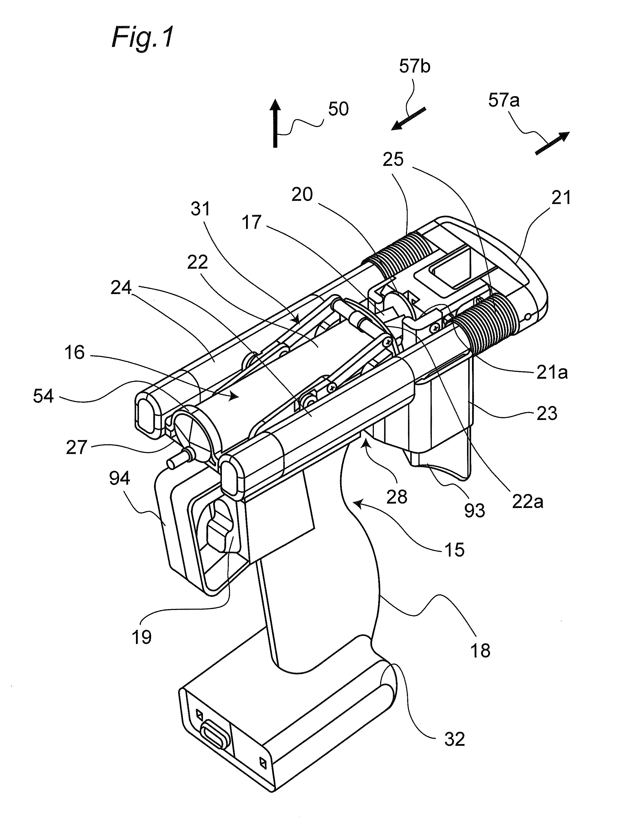
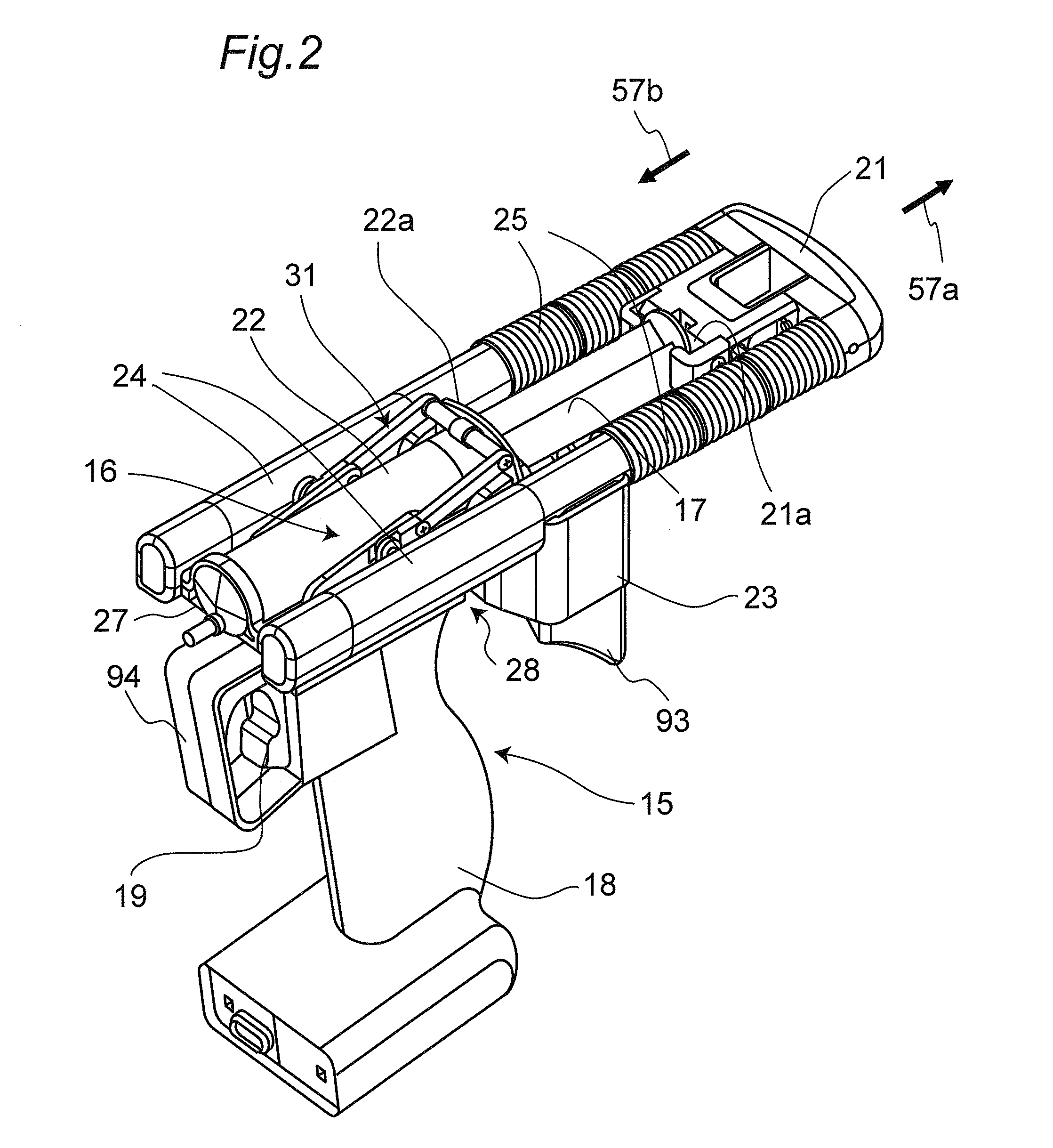
[0037]FIG. 1 is a perspective view of a syringe drive device according to the present embodiment 1. A syringe drive device 15 is a tool assisting in pushing and pulling a plunger 17 with respect to a syringe 16.

[0038]As shown in FIGS. 7(a) and 7(b), the syringe 16 includes an outer tube 22 having a distal end to which an injection needle 90 (see FIG. 21) is attached, and the plunger 17 having a distal end that is provided with a gasket 26 and is inserted into the outer tube 22 from an opening located far from the injection needle 90. The outer tube 22 has an open end provided with a flange portion 22a, and the plunger 17 has a rear end provided with a brim 20. In the following description, unless otherwise specified, a “front portion”, a “front surface”, and a “front end” each indicate a position at the distal end (close to the injection needle 90; in other words, the end toward which the plunger 17 is pushed) of the syringe 16. On the other hand, unless otherwise specified, a “rear...

embodiment 2

[0091]In a syringe drive device according to the present embodiment 2, the press portion includes a thickness adjuster that changes the distance from a syringe mounted on the outer tube fixing portion 31.

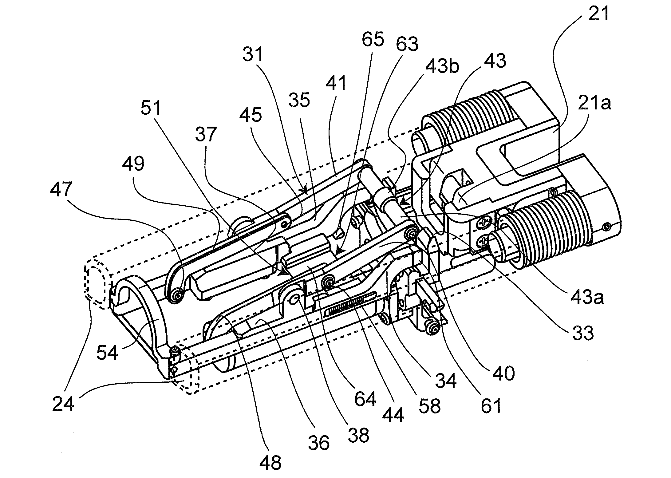
[0092]As shown in FIG. 5, in the syringe drive device 15 in the attached state, the distance between the slide portion 34 and the flange catcher 33 is determined by the degree of tilt of the input arm 40 due to the linking structure. The attached state is established when the press portion 43 coupled with the input arm 40 is in contact with the outer tube 22. Accordingly, the degree of tilt of the input arm 40 is varied depending on the outer diameter of the outer tube 22. Accordingly, the distance between the slide portion 34 and the flange catcher 33 is determined by the outer diameter of the outer tube 22. There will be no problem if the outer diameters of syringes 16 to be used in the syringe drive device 15 are all the same. However, if the syringe 16 of a different outer diame...

embodiment 3

[0101]A syringe drive device according to the present embodiment 3 is characterized in that the input arms are provided with lock portions to be coupled with the slide portions. In such a case where the lock portions are provided, the input arms are fixed reliably, so that the syringe can be fixed more stably.

[0102]FIG. 15 is a side view showing a main portion of the syringe drive device in the attached state. A slide portion 82 is shaped so as to be bent upward at a portion facing the flange catcher 33. The slide portion 82 and the flange 22a are in contact with each other at a contact portion 83, and an upper position of the contact portion 83 is coupled with a lock portion 84 that is provided at one end of the input arm 40.

[0103]FIG. 16 is a perspective view of the lock portion. The lock portion 84 is locked in FIG. 16. When a knob 85 of the lock portion 84 is pinched and moved along an arrow 86, the locking can be released easily. Moreover, the lock portion 84 has a press portio...


PUM


Abstract

A syringe drive device 15 according to the present invention includes: an outer tube fixing portion 31 that detachably fixes an outer tube 22 of a syringe 16; a plunger holder 21 that holds a plunger 17 of the syringe 16; and a drive portion that moves the plunger holder 21 along an axis of the syringe. The outer tube fixing portion 31 includes: a flange catcher 33 facing a rear end of a flange 22a of the outer tube 22, the rear end being located far from the plunger 17 to be pushed; slide portions 34 and 35 that are located in front of a front end of the flange 22a to hold the flange 22a between the flange catcher 33 and the slide portions, the front end being located close to the plunger 17 to be pushed; slide guides 36 and 37 that support the slide portions 34 and 35 so as to be slidable along the axis of the syringe; and a slide portion operation mechanism that is switchable between a first state where the slide portions 34 and 35 slide along the axis of the syringe, and a second state where the slide portions 34 and 35 are held at positions to hold the flange 22a between the flange catcher 33 and the slide portions.

Description

TECHNICAL FIELD[0001]The present invention relates to a syringe that is used for mixing medicinal solutions, etc. The present invention particularly relates to a syringe drive device that assists in pushing and pulling a plunger with respect to a syringe.BACKGROUND ART[0002]In the operation of mixing medicinal solutions, the medicinal solution in a vial is manually aspirated into a syringe to discharge the medicinal solution in the syringe. When medicinal solutions are mixed in a hospital, a plurality of operations are often performed at one time. Accordingly, it is quite a workload for a mixing person to push and pull a plunger with respect to a syringe in order to mix the medicinal solutions. For the purpose of reducing the workload of the mixing person, it has been considered a syringe drive device, which causes a plunger to be pushed and pulled by drive power of a motor.[0003]There is a syringe drive device (infusion solution transfer device) that causes a plunger to be pushed b...

Claims


Application Information

Patent Timeline
Patent Type & Authority Applications(United States)
IPC IPC(8): A61M5/145
CPCA61M5/1458A61M5/14546
Inventor FUJIOKA, SOICHIRONAKAMURA, TOHRUMIZUNO, OSAMUOKUDA, AKINOBUOHTA, AKIHIROSAKAKIBARA, MIZUHOUEDA, TOSHIHIDE
Owner PANASONIC CORP
Why Eureka
Try Eureka