
Zygomatic elevator device and methods

a technology of elevator device and zygomatic arch, which is applied in the field of zygomatic arch, can solve the problems of difficulty in correctly controlling the location of the elevator device relative to the fracture, the magnitude and direction of the force applied to reduce the fracture, etc., and achieves the effect of reducing the fracture and reducing the fractur

Active Publication Date: 2012-12-27
UNIV OF MASSACHUSETTS
View PDF35 Cites 13 Cited by
  • Summary
  • Abstract
  • Description
  • Claims
  • Application Information

AI Technical Summary

Benefits of technology

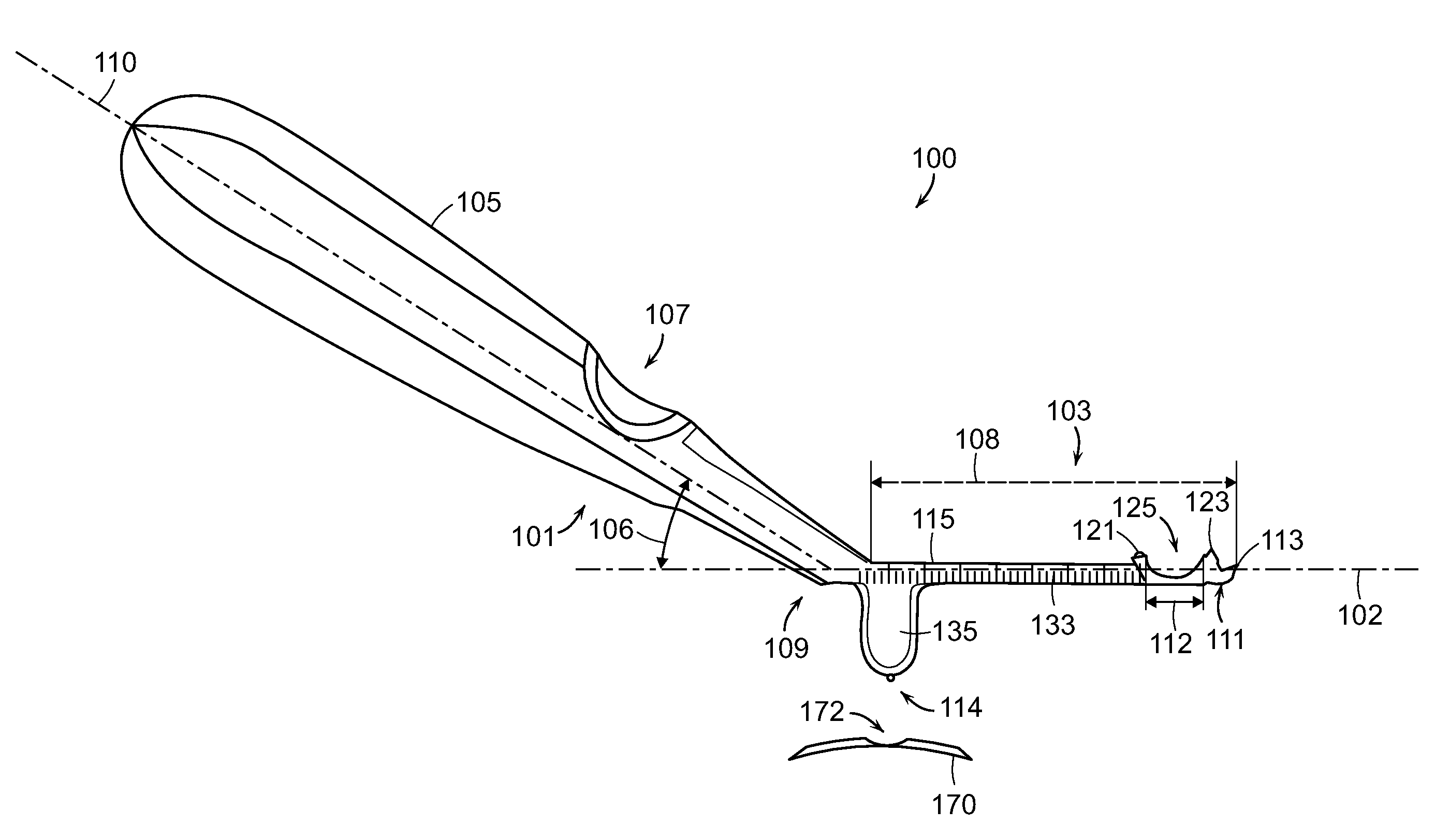
[0005]The present invention comprises a surgical elevator device that can be used in the reduction of bone fractures, particularly facial bone fractures, and even more particularly zygomatic arch fractures. The present elevator device enables accurate measurement of the depth of insertion of the device into position adjacent the skeletal feature of interest, provides tactile control of fracture location and reduction, and permits improved control of the magnitude and direction of the force applied to reduce fractures.
[0009]According to yet another embodiment, a method of reducing a fractured bone using a surgical elevator device comprises making an incision over the temporal bone to enable percutaneous insertion of the elevator element into a subject by manipulating a handle portion of the elevator device; positioning a distal end of the elevator element beneath the fractured bone so that the bone is received by a groove on the first surface; positioning a base extending from a surface of the elevator device against an (extraoral) external surface feature of the subject to provide a pivot point; and rotating the handle towards the subject, using the projection as a pivot, to transfer a substantially lateral outward force to the fractured bone positioned in the groove to reduce the fracture. The user, such as a surgeon, can simultaneously palpate the external surface of the tissue overlying the bone. In a preferred embodiment, the fractured bone comprises a zygomatic arch.

Problems solved by technology

With existing techniques, it is often difficult to correctly control the location of the elevator device relative to the fracture, as well as the magnitude and direction of the force applied to reduce the fracture.

Method used


Image

  • Zygomatic elevator device and methods
  • Zygomatic elevator device and methods
  • Zygomatic elevator device and methods

Examples


Embodiment Construction

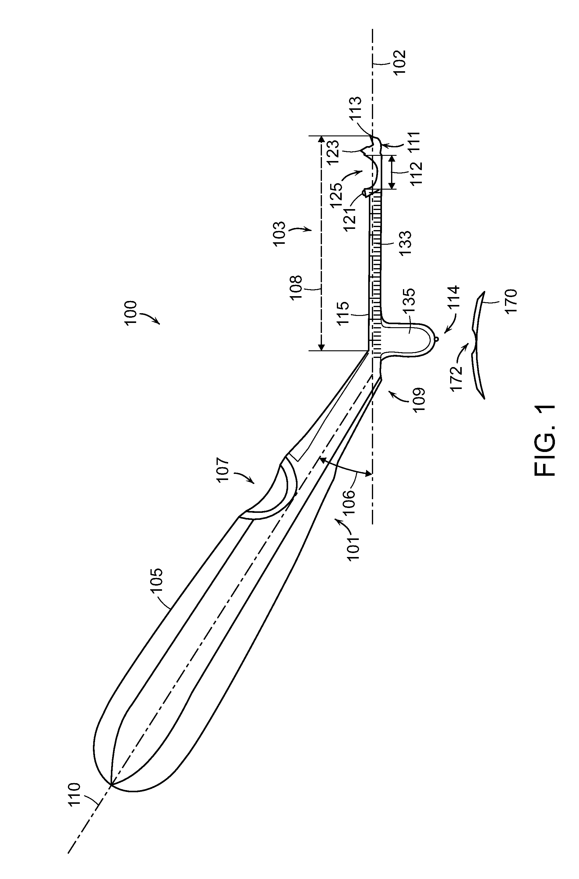
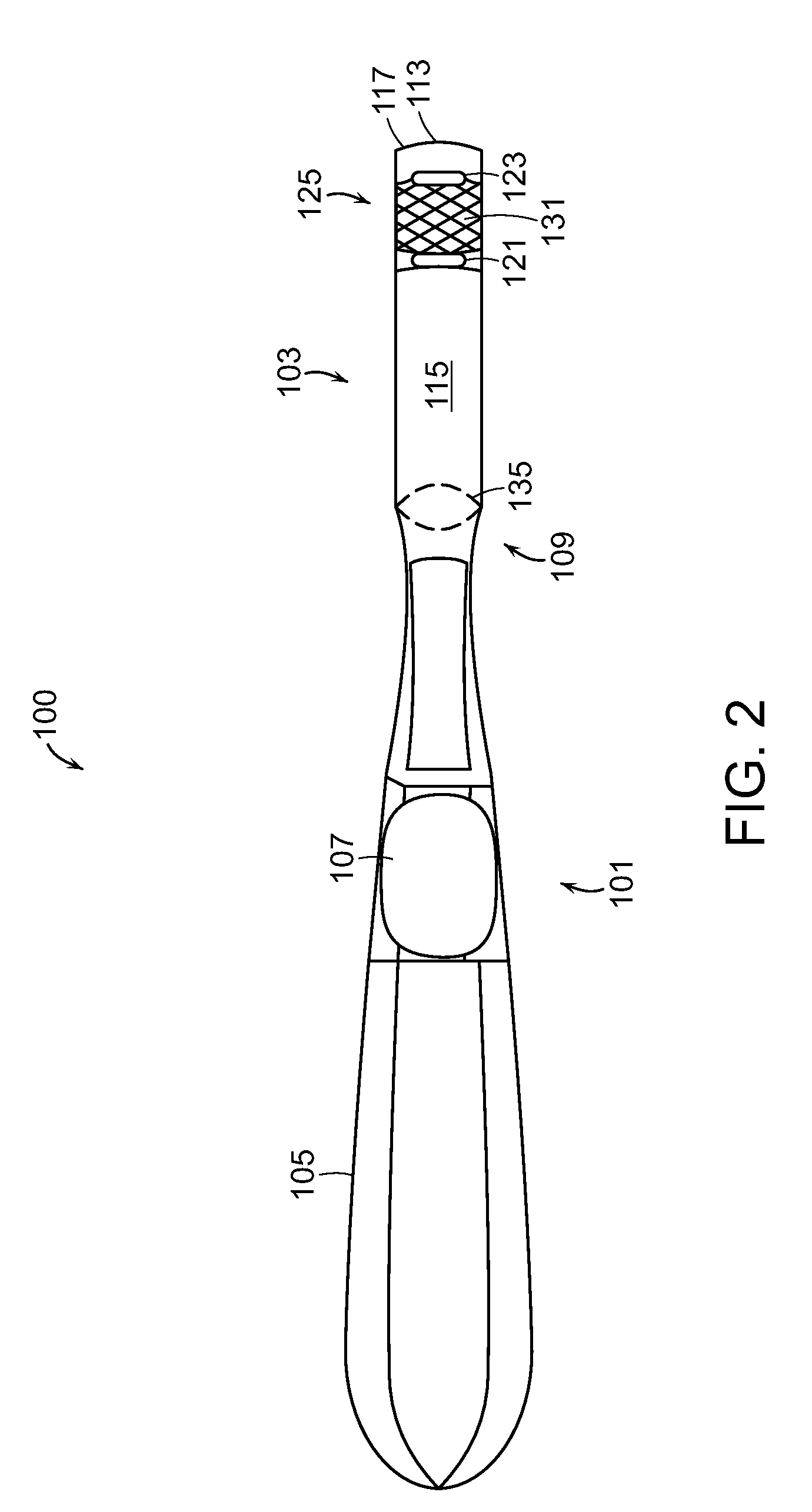
[0019]Referring now to FIGS. 1-4B, an elevator device 100 for use in a surgical procedure, for instance, for the reduction of a zygomatic arch fracture, is illustrated. The elevator device 100 generally includes a handle portion 101 and a elevator element 103. The elevator element portion 103 can be angled with respect to the handle portion 101, such as shown in the side-view of FIG. 1. This angle 106 can be between 20 and 70 degrees, preferably in a range of 30 to 60 degrees. The angle 106 between the handle axis 110 and the elevator axis 102 is thus preferably at least 20 degrees to provide sufficient clearance from the head of the user. The handle portion 101 can include a grip 105 that allows the device 100 to be easily grasped and manipulated by a user. The grip 105 can further include a groove 107 that is positioned to receive the thumb of a user for more precise control of the device 100.

[0020]The elevator element 103 includes a proximal end 109, where the element 103 connect...


PUM


Abstract

A surgical elevator device that can be used in the reduction of bone fractures, particularly facial bone fractures, and even more particularly zygomatic arch fractures. The elevator device enables accurate measurement of the depth of insertion of the device into tissue space and provides tactile control of fracture location and reduction. In one embodiment, the elevator device comprises a groove on an elevator element for receiving a bone structure. The groove can be formed by a pair of parallel ridges. A projection extending from the elevator provides a pivot point for applying a controlled force to the bone to reduce the fracture. A preferred embodiment further comprises a method of reducing a bone fracture, such as a zygomatic arch fracture.

Description

CROSS REFERENCE TO RELATED APPLICATIONS[0001]The application claims priority to U.S. Provisional Application No. 61 / 310,950 filed on Mar. 5, 2010, the entire contents of which is incorporated herein by reference.BACKGROUND OF THE INVENTION[0002]The zygomatic arch is a bone structure located in the cheek area of the face that extends between the zygoma and the temporal bone. Because of the position and prominence of this structure, fractures of the zygomatic arch are a relatively common type of facial injury.[0003]To treat zygomatic arch fractures, various techniques are used to re-set or “reduce” the fracture, by restoring the injured structure to its normal anatomic position. In some cases, this can be done non-invasively by a “closed reduction,” in which the bone is restored by external manipulation without requiring an incision. Frequently, however, an “open reduction” is needed, which requires a surgical incision for reduction, and optional internal fixation, of the fractured zy...

Claims


Application Information

Patent Timeline
IPC IPC(8): A61B17/56
CPCA61B17/8866A61B17/025A61B17/0218A61B17/885
Inventor DUNN, RAYMOND M.
Owner UNIV OF MASSACHUSETTS
Learn More