Control apparatus and refrigerating apparatus

Active Publication Date: 2013-01-03
PANASONIC HEALTHCARE HLDG CO LTD
View PDF4 Cites 6 Cited by
  • Summary
  • Abstract
  • Description
  • Claims
  • Application Information

AI Technical Summary

Benefits of technology

The control apparatus described in this patent is designed to control a refrigerating apparatus that includes a compressor and a circuit breaker. The circuit breaker is designed to interrupt the current when it becomes too high, while the control unit is designed to trip the circuit breaker when the voltage of the power supply becomes too low. This helps to prevent the compressor from operating at an overcurrent condition, which can damage the apparatus. The technical effect of this invention is to improve the safety and reliability of the refrigerating apparatus.

Problems solved by technology

A compressor provided in a refrigerating apparatus may lock due to some abnormalities such as overheating and a slow leak of a refrigerant.
When the compressor locks an overcurrent flows, and if such a situation is left as it is, then a coil of the compressor motor burns out, leading to destruction of the compressor.
It is desirable that the abnormality causing locking of the compressor is resolved within a Short time, but if the abnormality continues for a long time, the protection circuit is turned on and off repeatedly, possibly resulting in welding of the bimetal in the worst case.
On the other hand, in a so-called ultracold freezer configured to contain biotic samples and cool an inside of the freezer to a temperature lower than or equal to −80° C., if cooling capacity is lost due to problems such as locking of the compressor, precious biotic samples contained therein is damaged.
Incidentally, when a power supply voltage fluctuates, a voltage drop may cause the compressor to lock.

Method used


Image

  • Control apparatus and refrigerating apparatus
  • Control apparatus and refrigerating apparatus
  • Control apparatus and refrigerating apparatus

Examples


Embodiment Construction

[0016]At least the following details will become apparent from descriptions of this specification and of the accompanying drawings.

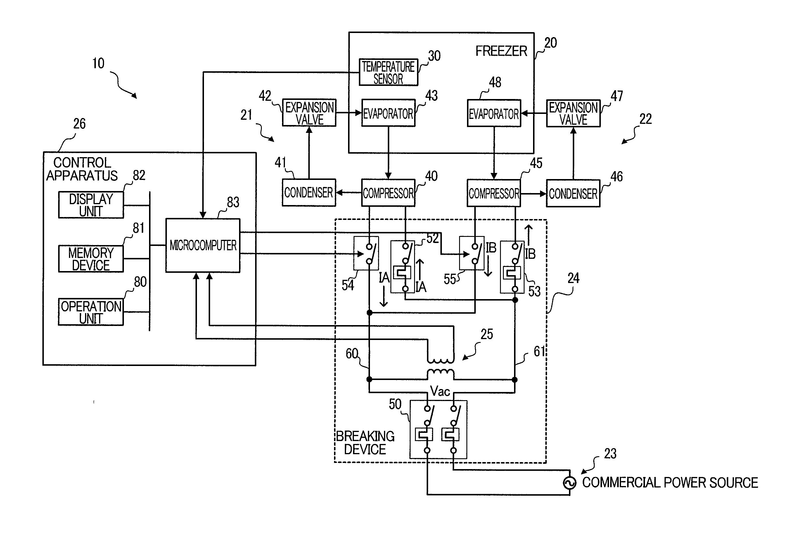
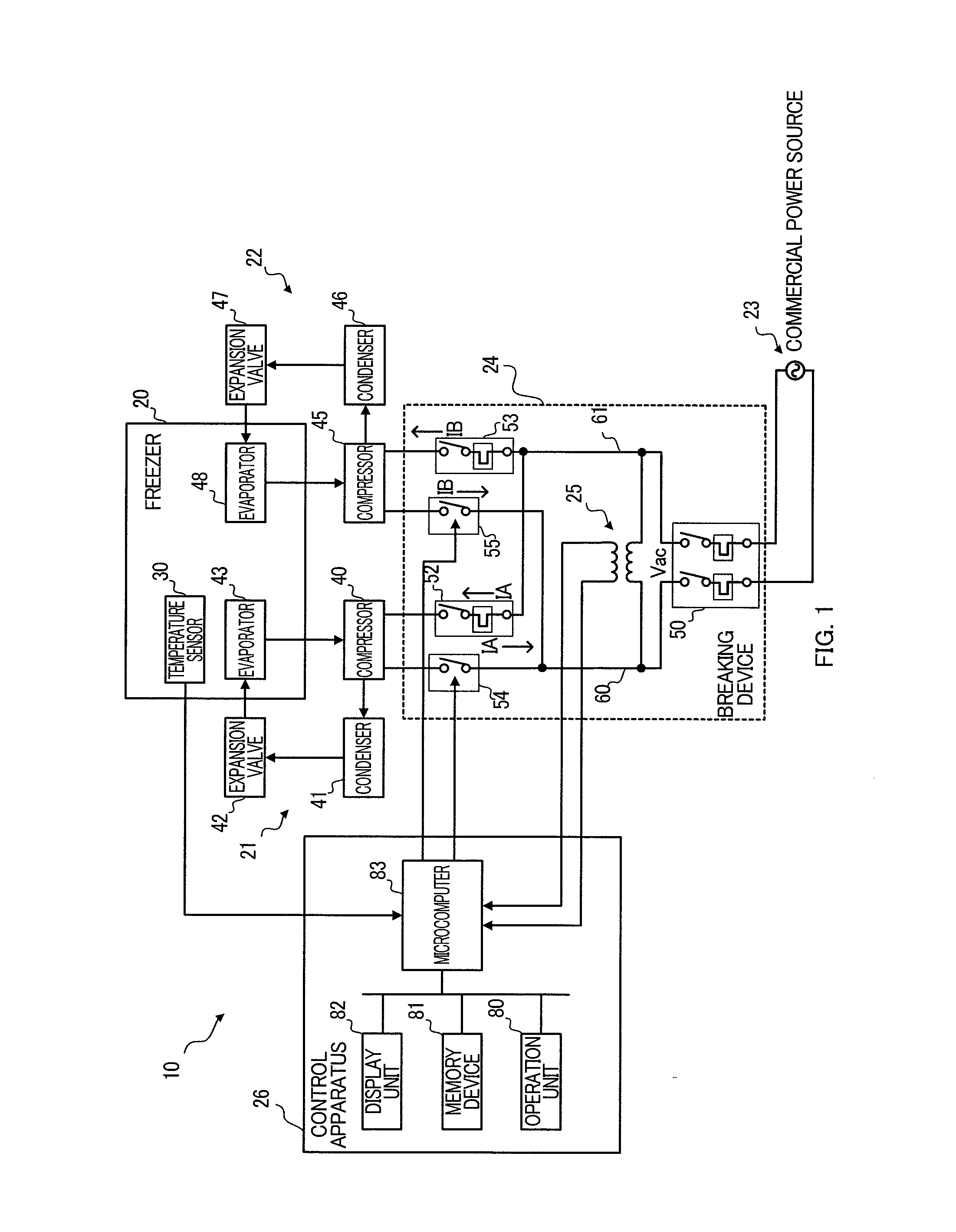
[0017]FIG. 1 depicts a configuration of a refrigerating apparatus 10 according to an embodiment of the present invention. The refrigerating apparatus 10 includes a freezer 20, refrigerant circuits 21 and 22, a commercial power supply 23, a breaking device 24, a transformer 25, and a control apparatus 26.

[0018]The freezer 20 stores frozen items, body tissues, etc., at an ultralow temperature of −80° C., for example. The freezer 20 includes a temperature sensor 30 configured to output a voltage corresponding to a temperature inside the freezer.

[0019]The refrigerant circuit 21 is a circuit configured to cool an inside of the freezer 20, and includes a compressor 40, a condenser 41, an expansion valve 42, and an evaporator 43.

[0020]The compressor 40 (first compressor) is configured to suck refrigerant evaporated by the evaporator 43, and thereafter compress ...


PUM


Abstract

A control apparatus, which controls a refrigerating apparatus including a compressor and a first circuit breaker that interrupts a current flowing through the compressor when the current, flowing from a power supply through the compressor to cause the compressor to work, becomes greater than a predetermined current and that is closed according to an operation by a user, includes: a voltage-measuring unit to measure a power-supply voltage a control unit to trip a second circuit breaker disposed in series with the first circuit breaker so that the current from the power supply flowing through the compressor is interrupted, when the measured power-supply voltage becomes lower than a predetermined voltage, and close the second circuit breaker after the power-supply voltage becomes higher than the predetermined voltage, the predetermined current corresponding to a current greater than the current flowing through the compressor when the power-supply voltage is equal to the predetermined voltage.

Description

CROSS-REFERENCE TO RELATED APPLICATION[0001]This application claims the benefit of priority to Japanese Patent Application No. 2010-293582, filed Dec. 28, 2010, of which full contents are incorporated herein by reference.BACKGROUND OF THE INVENTION[0002]1. Field of the Invention[0003]The present invention relates to a control apparatus and a refrigerating apparatus.[0004]2. Description of the Related Art[0005]A compressor provided in a refrigerating apparatus may lock due to some abnormalities such as overheating and a slow leak of a refrigerant. When the compressor locks an overcurrent flows, and if such a situation is left as it is, then a coil of the compressor motor burns out, leading to destruction of the compressor. Thus, a common refrigerating apparatus includes a protection circuit (e.g., overload relay of bimetal, etc.) to protect the compressor against overcurrent or overheating. It is desirable that the abnormality causing locking of the compressor is resolved within a Sh...

Claims


Application Information

Patent Timeline
IPC IPC(8): F25B49/02
CPCF25B2700/151F25B49/025F25B49/02F25D29/00
Inventor TSURUMA, RYUICHI
Owner PANASONIC HEALTHCARE HLDG CO LTD
Why Eureka
Try Eureka