Respiration system for an anesthesia apparatus

a technology of anesthesia apparatus and respiration system, which is applied in the direction of respirator, inhalator, etc., can solve the problems of complicating the system described further, unable to reliably operate the evaporator, etc., and achieves the effect of rapid oxygen flushing of the entire breathing circui

Active Publication Date: 2013-01-03
DRAGERWERK AG
View PDF18 Cites 7 Cited by
  • Summary
  • Abstract
  • Description
  • Claims
  • Application Information

AI Technical Summary

Benefits of technology

[0017]An object of the present invention is therefore to provide a respiration system for an anesthesia apparatus, which is controlled in a less complicated manner and makes possible rapid flushing of the entire breathing circuit with oxygen.

Problems solved by technology

However, such a system is associated with the drawback that a gas flow must be continuously maintained in the breathing circuit in order to ensure that the oxygen is also distributed in the entire breathing circuit, and it does not happen that parts thereof are not flushed.
Another problem in closed respiration systems is that it is desirable, on the one hand, to provide a constant fresh gas flow from the fresh gas supply unit, which flow is now flowing through an anesthetic evaporator, so that this constant flow can be used in the evaporator to absorb the anesthetic.
Such an evaporator cannot be operated reliably if the intensity of the flow varies as a result and if a pulsed flow is used.
This complicates the system described further.

Method used


Image

  • Respiration system for an anesthesia apparatus
  • Respiration system for an anesthesia apparatus
  • Respiration system for an anesthesia apparatus

Examples


Embodiment Construction

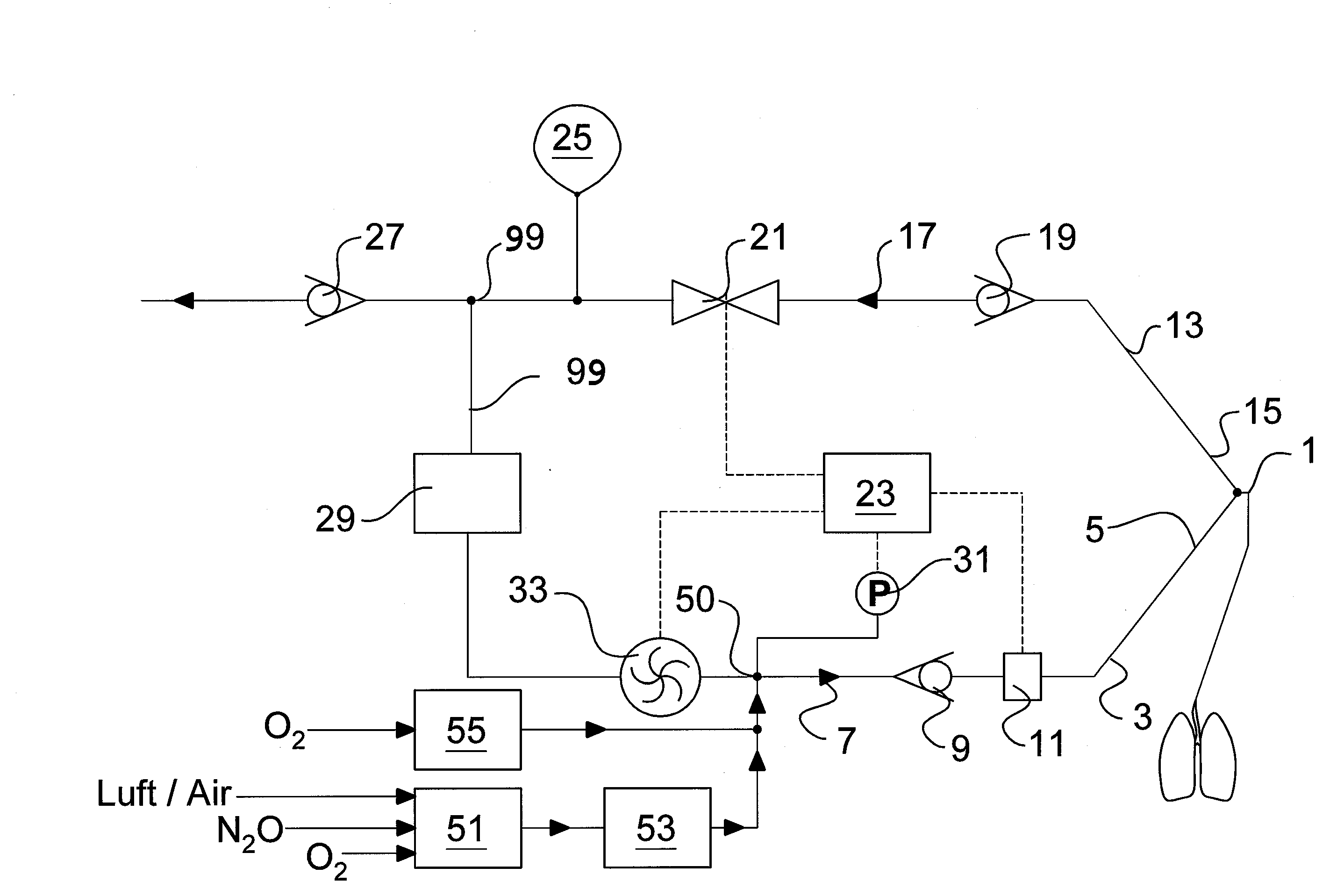
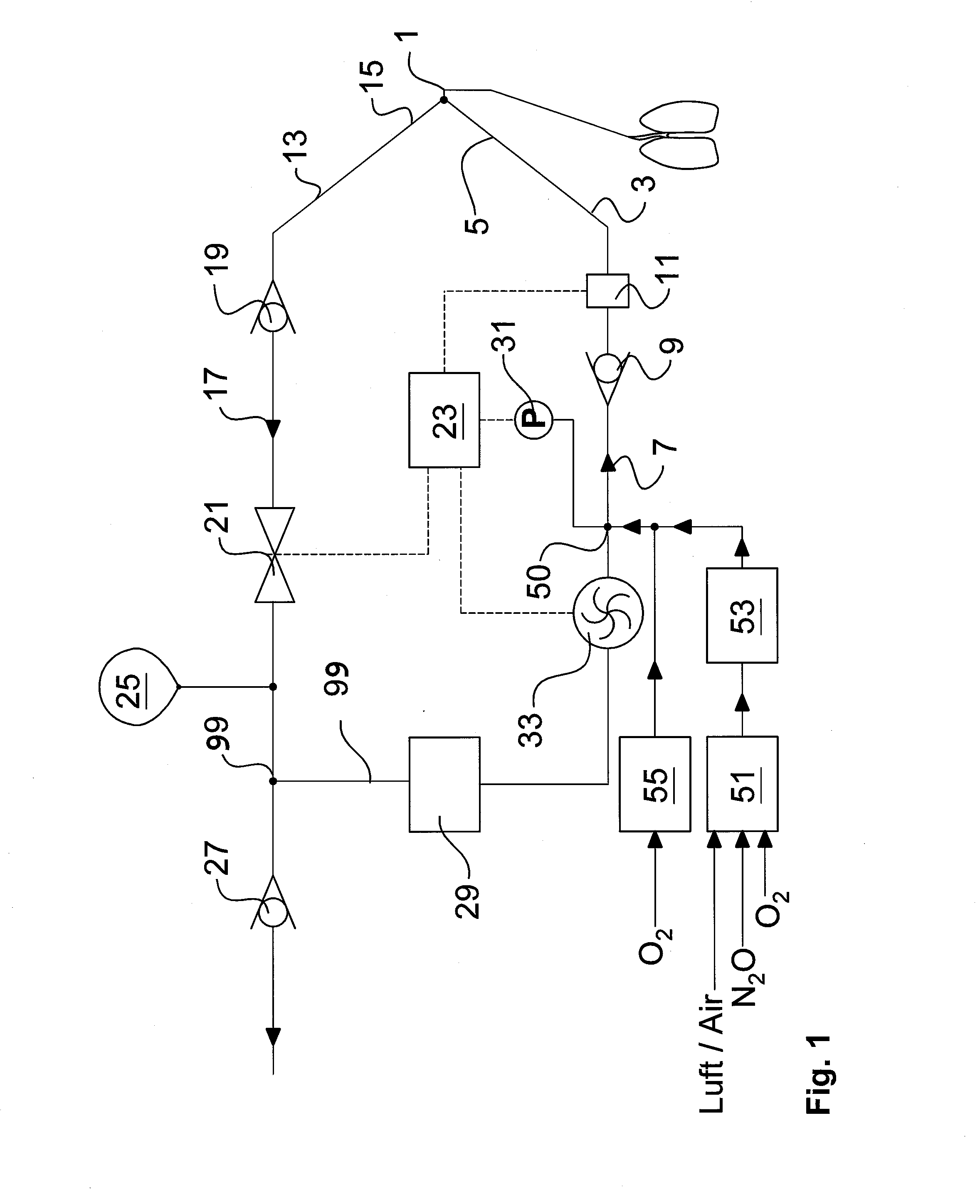
[0042]Referring to the drawings in particular, the first exemplary embodiment of a respiration system, which is shown in FIG. 1, has a patient connection 1, which is designed as a Y-piece and from which an inspiratory branch 3 extends, which has a first end 5, which is arranged adjacent to the patient connection 1, and a second end 7, which is located away from the patient connection 1. In addition, a nonreturn valve 9, which is designed such that it opens when the pressure on the side of the nonreturn valve 9 facing the second end 7 is higher than the pressure on the side pointing towards the first end 5, is provided in the inspiratory branch 3. In particular, nonreturn valve 9 is designed such that it opens only when the difference between the pressure on the side pointing towards the second end 7 and that on the side pointing towards the first end 5 is above a preset threshold. It is ensured by this design that gas expired by the patient and discharged from the patient connection...


PUM


Abstract

A respiration system includes a patient connection (1), an inspiratory branch (3), an expiratory branch (13), a rebreathing line (99), a reservoir (25), a CO2 absorber (29), a radial compressor respiration drive (33), a fresh gas supply unit (51), an oxygen flushing device (55), connected to the rebreathing line, a pressure sensor (31) and an actuatable control valve (21), arranged in the rebreathing line between a second end (17) of the expiratory branch and the CO2 absorber. The compressor, oxygen flushing device and fresh gas supply unit are arranged in the rebreathing line between the CO2 absorber and a second end (7) of the inspiration branch. The compressor inlet points towards the CO2 absorber and the outlet points towards the second end of the inspiratory branch. The pressure sensor is arranged in the rebreathing line between the compressor and the second end of the inspiratory branch.

Description

CROSS REFERENCE TO RELATED APPLICATIONS[0001]This application claims the benefit of priority under 35 U.S.C. §119 of German Utility Model Application DE 20 2011 102 764.7 filed Jul. 2, 2011, the entire contents of which are incorporated herein by reference.FIELD OF THE INVENTION[0002]The present invention pertains to a respiration system (also known as a ventilation system) for an anesthesia apparatus with a patient connection, with an inspiratory branch, with an expiratory branch, with a rebreathing line, which connects the inspiratory branch to the expiratory branch, with a fresh gas supply unit, with an oxygen flushing means and with a radial compressor as a respiration drive, which is arranged in the rebreathing line.BACKGROUND OF THE INVENTION[0003]Anesthesia devices with an inspiratory branch and an expiratory branch are shown in the state of the art. So-called half-closed anesthesia systems are used for reusing the portion of anesthesia gas in the expired gas. Such a half-clo...

Claims


Application Information

Patent Timeline
Patent Type & Authority Applications(United States)
IPC IPC(8): A61M16/22A61M16/20A61M16/01
CPCA61M16/0051A61M16/0066A61M16/01A61M16/104A61M16/1015A61M2016/0027A61M2016/0039A61M16/0069A61M16/22A61M16/0858A61M16/022
Inventor HEESCH, RALF
Owner DRAGERWERK AG
Why Eureka
Try Eureka