
Solid cone nozzle

a solid cone and nozzle technology, applied in the direction of spray nozzles, spraying apparatus, etc., can solve the problems of hollow cone jets, and achieve the effect of preventing the choking effect of swirl ducts and being less susceptible to choking problems

Active Publication Date: 2013-01-03
LECHLER SPA
View PDF11 Cites 3 Cited by
  • Summary
  • Abstract
  • Description
  • Claims
  • Application Information

AI Technical Summary

Benefits of technology

The patent text describes a nozzle design that can achieve a more uniform pressure balance and a more stable flow of fluid. This design helps to prevent clogging and reduces the resistance to flow. Additionally, it improves the distribution of fluid in the resultant solid cone jet, leading to a more uniform output. Overall, the design provides a more reliable and efficient nozzle for industrial applications.

Problems solved by technology

If the static pressure at the center of the outlet chamber and thus in the region of the axis of rotation is too low, it results in a hollow cone jet.

Method used


Image

  • Solid cone nozzle
  • Solid cone nozzle
  • Solid cone nozzle

Examples


Embodiment Construction

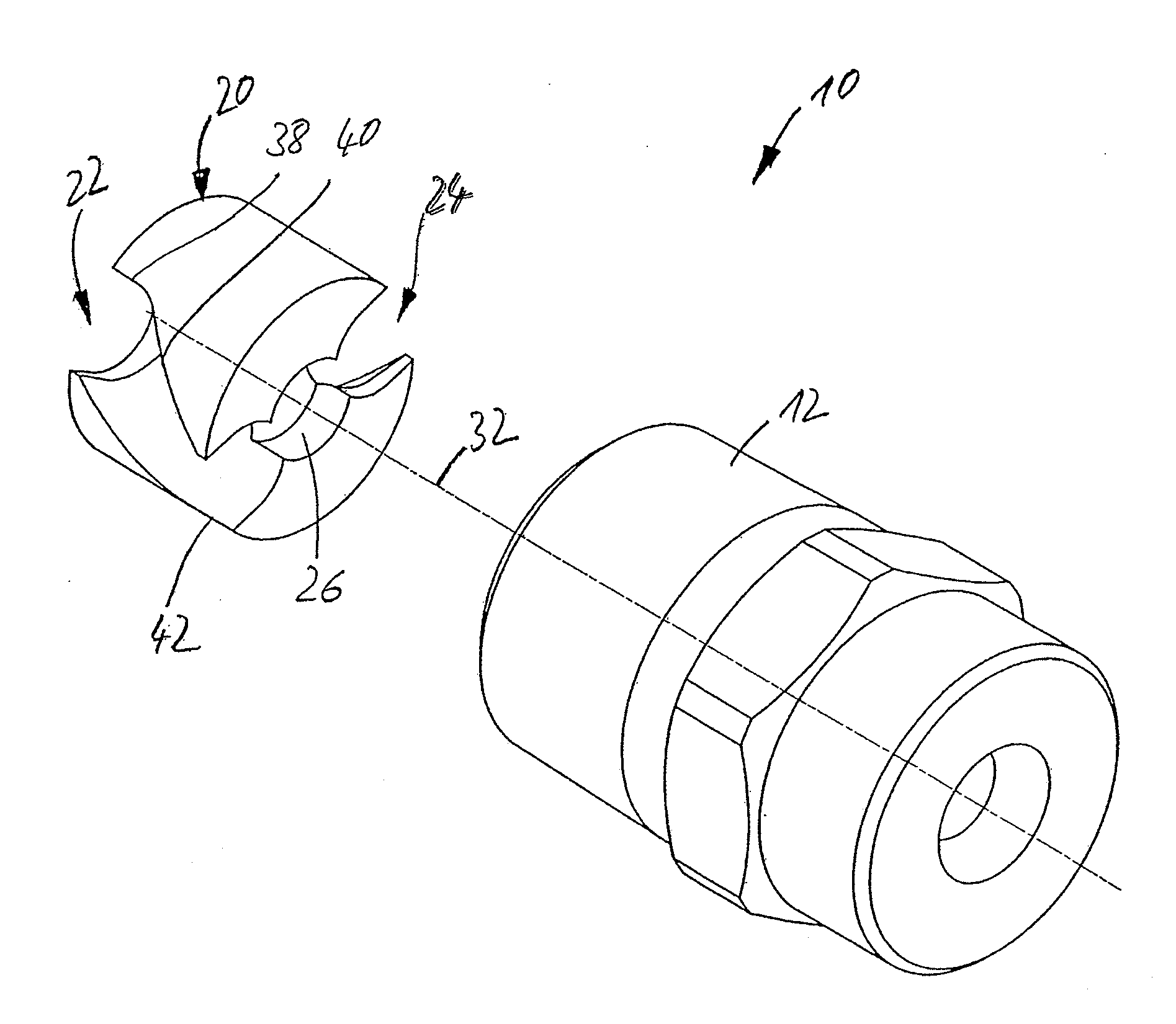
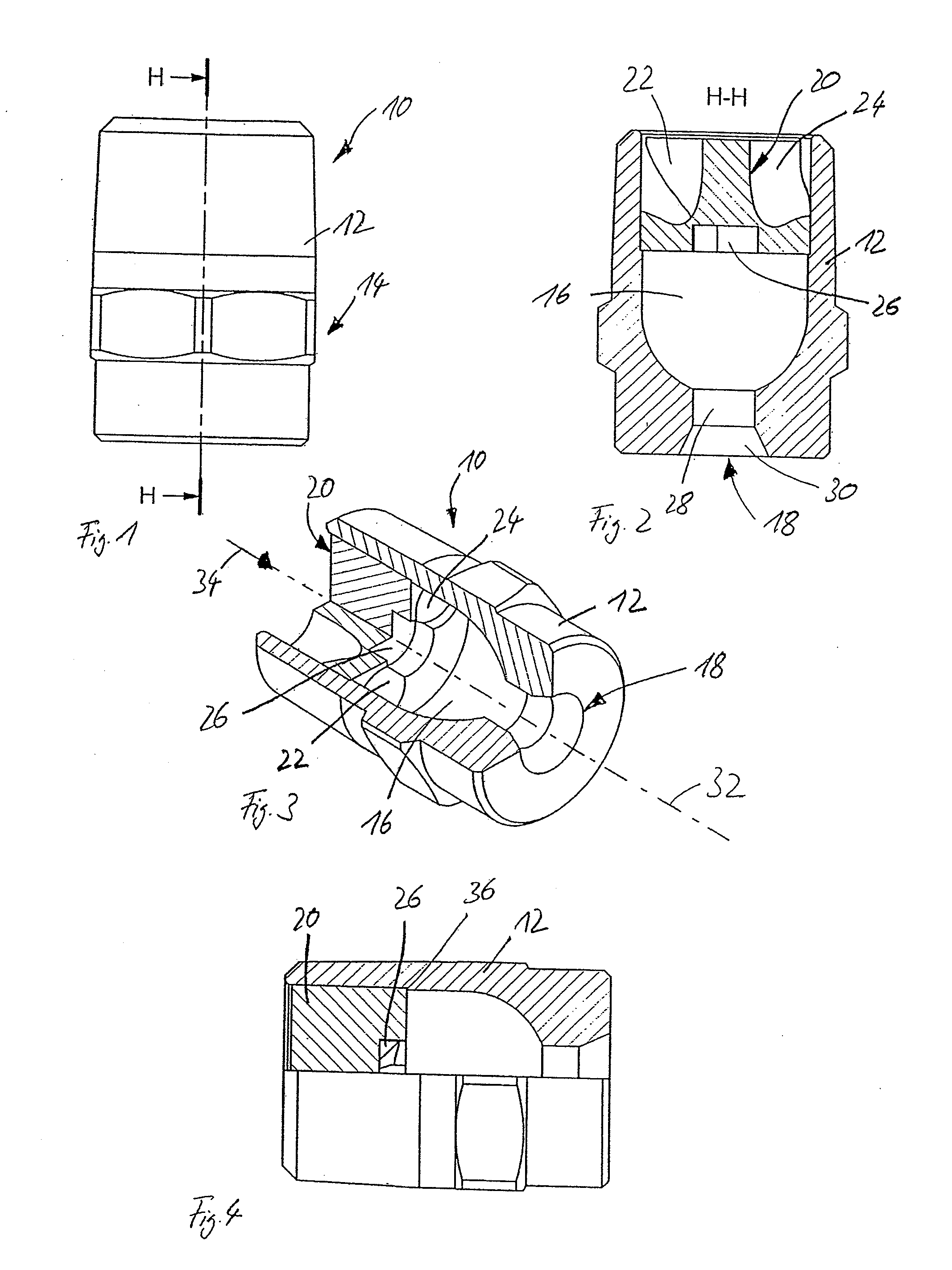
[0063]FIG. 1 shows a solid cone nozzle 10 of the invention according to a preferred embodiment of the invention. The solid cone nozzle 10 has a housing 12 that is provided with a hexagonal profile 14 and a screw thread (not shown in the figure) to enable the housing to be screwed onto a connecting line. The housing 12 has a generally cylindrical shape.

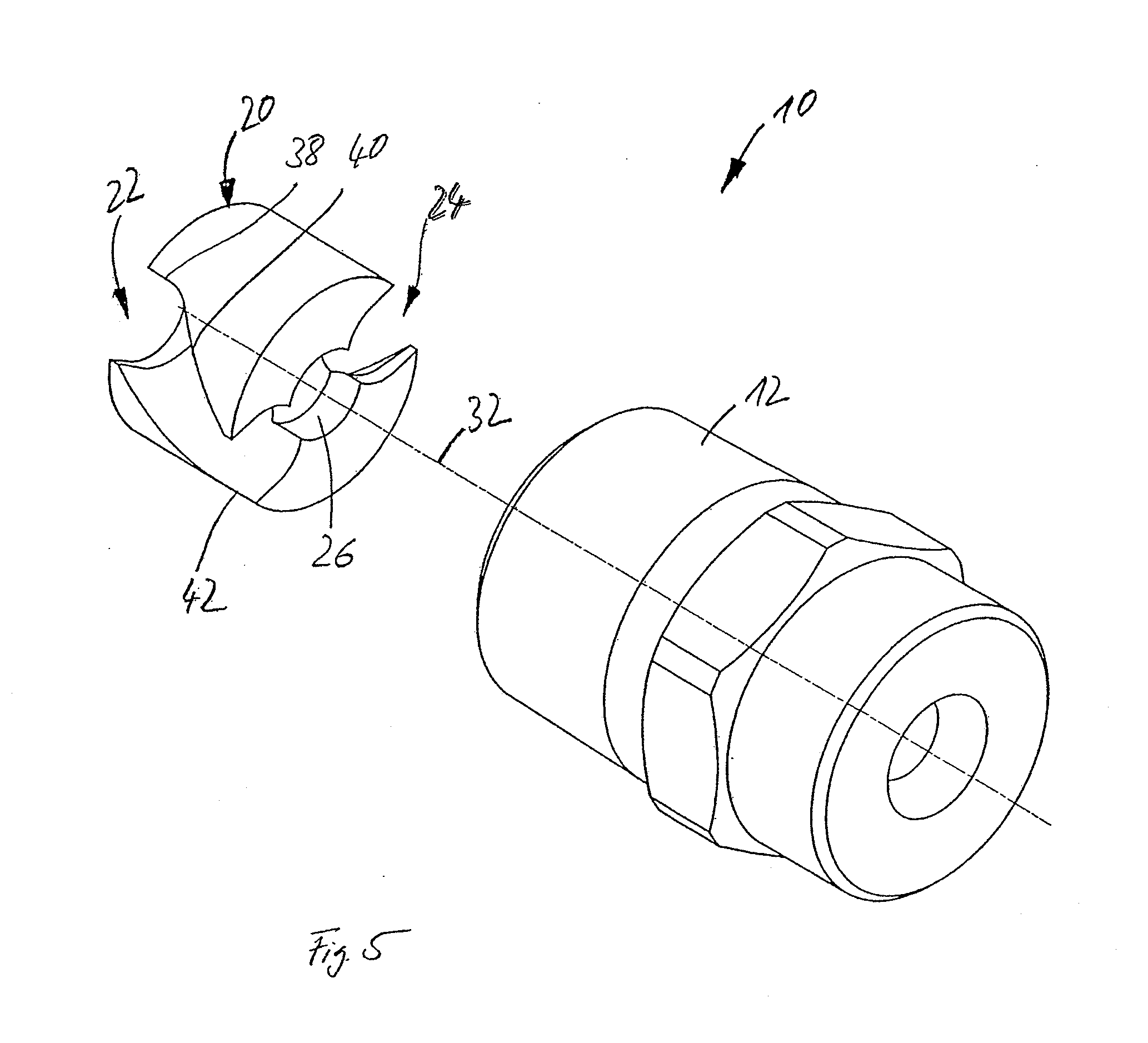
[0064]FIG. 2 is a view of the cross-sectional plane H-H indicated in FIG. 1. The housing 12 has an outlet chamber 16 and an outlet orifice 18. There is disposed a swirl insert 20 upstream of the outlet chamber 16 in the housing 12. The swirl insert 20 is basically disk-shaped and is provided with two swirl ducts 22, 24 on its external periphery. At its end face in proximity to the outlet chamber 16, the swirl insert is provided with a central recess 26 in the form of a blind hole having a plane base and a circular cross-section.

[0065]The outlet chamber 16 is of a plain cylindrical shape in its region adjacent to the swirl insert 20. Do...


PUM


Abstract

A solid cone nozzle comprises a nozzle housing and a swirl insert, wherein said nozzle housing has an outlet chamber including a discharge orifice and wherein the outlet chamber is disposed downstream of the swirl insert. The swirl insert has on its external periphery at least one swirl duct, which extends, in a swirl portion, helically or at an angle to the longitudinal center axis of the swirl insert and which extends in the axial direction in an outlet portion, which outlet portion extends from the end of the swirl portion to the downstream end of the swirl duct.

Description

CROSS REFERENCE TO RELATED APPLICATION[0001]This application claims the priority of German Application No. 10 2011 078 508.6, filed Jul. 1, 2011, the disclosure of which is hereby incorporated by reference in its entirety into this application.FIELD OF THE INVENTION[0002]The invention relates to a solid cone nozzle comprising a housing and a swirl insert, in which the housing has an outlet chamber including an outlet orifice and in which the outlet chamber is disposed downstream of the swirl insert.SUMMARY OF THE INVENTION[0003]It is an object of the present invention to provide an improved solid cone nozzle.[0004]To this end, the invention provides a solid cone nozzle comprising a housing and in which a swirl insert, in which the housing has an outlet chamber including an outlet orifice and the outlet chamber is disposed downstream of the swirl insert, wherein the swirl insert has on its external periphery at least one swirl duct that extends, in a swirl portion, helically or at an...

Claims


Application Information

Patent Timeline
IPC IPC(8): B05B1/34
CPCB05B1/3447
Inventor SCHNEIDER, MATTHIAS
Owner LECHLER SPA
Learn More