Magnetic gear arrangement

a gear arrangement and magnetic technology, applied in the direction of synchonous clutch/brake, dynamo-electric brake control, superconductor element usage, etc., can solve the problem of assembling permanent magnets into such gear arrangements

Active Publication Date: 2013-01-03
ROLLS ROYCE PLC
View PDF9 Cites 23 Cited by
  • Summary
  • Abstract
  • Description
  • Claims
  • Application Information

AI Technical Summary

Benefits of technology

[0082]Preferably, the interpoles are formed entirely by the regions. In this way, cooling the regions below the critical temperature prevents the coupling device from transmitting torque between the first and the second gear members. That is, the gear arrangement can have a clutch functionality.
[0083]The magnetic gear arrangement may further comprise a separator element between the first gear member and the second gear member, the separator element being formed of a superconducting material, wherein the separator element prevents or discourages magnetic flux extending between the first and second gear members but bypassing the coupling device. Preferably, the critical temperature of the separator element is equal to or greater than the critical temperature of the superconducting body, so that when the separator eleme

Problems solved by technology

A problem arises, however, of assembling the permanent magnets into such gear

Method used


Image

  • Magnetic gear arrangement
  • Magnetic gear arrangement
  • Magnetic gear arrangement

Examples


Embodiment Construction

Coupling Devices Comprising a Plurality of Superconducting Pole Elements

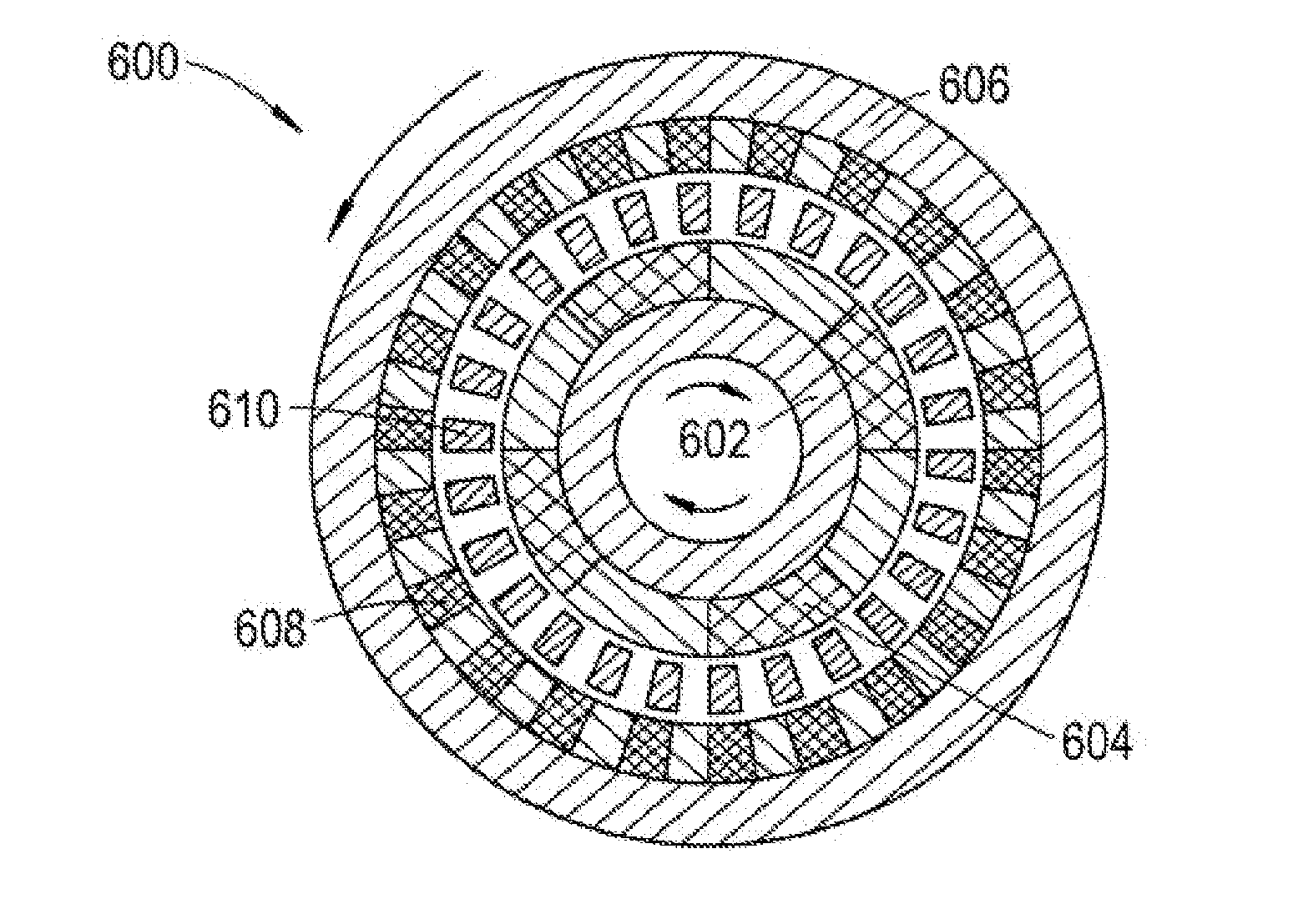
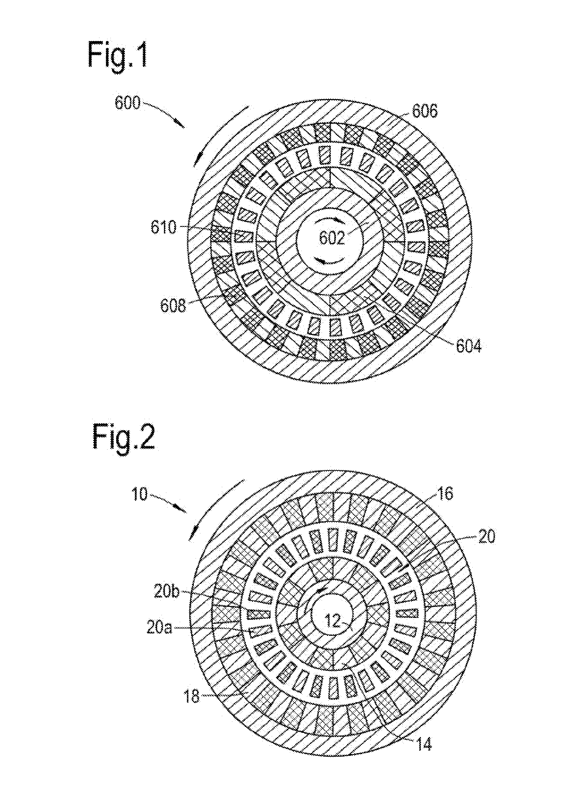
[0126]FIG. 2 shows a schematic cross-sectional view of a magnetic gear arrangement according to an embodiment of the present invention. The magnetic gear arrangement is in the form of an epicyclic gearbox 10 and comprises an inner rotor 12 (i.e. a first gear member) and an outer rotor 16 (i.e. a second gear member). Superconducting permanent magnets fixed to the inner and outer rotors provide respective pole pairs 14, 18, the opposite polarities of each magnet being respectively indicated by dark and light shading. The magnets affixed to the inner rotor have alternating polarity along the circumference of the rotor. Similarly, the magnets affixed to the outer rotor have alternating polarity along the circumference of that rotor. Typically, one rotor is mechanically coupled to a drive mechanism and the other rotor is mechanically coupled to a driven mechanism.

[0127]The inner and outer rotors 12, 16 have different...


PUM


Abstract

A magnetic gear arrangement includes: a first gear member for generating a first magnetic field, a second gear member for generating a second magnetic field, and a coupling device which provides an arrangement of interpoles between the first gear member and the second gear member. The interpoles couple the first and second magnetic fields to produce a gearing between the first and second gear members. The first gear member has superconducting magnets or coils for generating the first magnetic field and/or the second gear member has superconducting magnets or coils for generating the second magnetic field.

Description

FIELD OF THE INVENTION[0001]The present invention relates to magnetic gear arrangements, and for example to magnetic gear arrangements having a variable gear ratio.BACKGROUND OF THE INVENTION[0002]Gearboxes and gear arrangements are utilised in a wide range of situations in order to couple drive mechanisms. Traditionally, gearboxes have been formed from gear wheels having appropriate teeth numbers and sizes to provide a desired gear ratio. However, such gearboxes have a number of disadvantages. Firstly, they require the use of lubricating oils, which may act as contaminants or fire hazards and may prove ineffective in hot or cold environments, where the oil viscosity varies, or in a low pressure environment, where the oil may evaporate. Furthermore, gearboxes based on gear wheels may be noisy, making them unacceptable for low noise environments such as in hospitals, libraries and residential areas, or for clandestine military activities.[0003]More recently, magnetic gearboxes have b...

Claims


Application Information

Patent Timeline
IPC IPC(8): H02K49/10
CPCH02K49/06Y02E40/62H02K55/00H02K49/102H02K15/125H02K2213/09Y02E40/60
Inventor EDWARDS, HUW LLEWELYNBRIGHT, CHRISTOPHER GRAHAM
Owner ROLLS ROYCE PLC
Why Eureka
Try Eureka