Eureka AIR delivers breakthrough ideas for toughest innovation challenges, trusted by R&D personnel around the world.

Semiconductor integrated circuit for regulator

a technology of integrated circuit and regulator, which is applied in the direction of electric variable regulation, process and machine control, instruments, etc., can solve the problems of increasing wasteful current, proving poor switching response characteristics, and taking a long time to bring the output voltage vsub>out /sub>, so as to improve the transient response characteristics and increase the effect of wasteful curren

Inactive Publication Date: 2013-01-03
MITSUMI ELECTRIC CO LTD
View PDF11 Cites 23 Cited by
  • Summary
  • Abstract
  • Description
  • Claims
  • Application Information

AI Technical Summary

Benefits of technology

This invention aims to offer a semiconductor integrated circuit for regulators that can improve the speed at which voltage is switched without causing unnecessary electricity usage.

Problems solved by technology

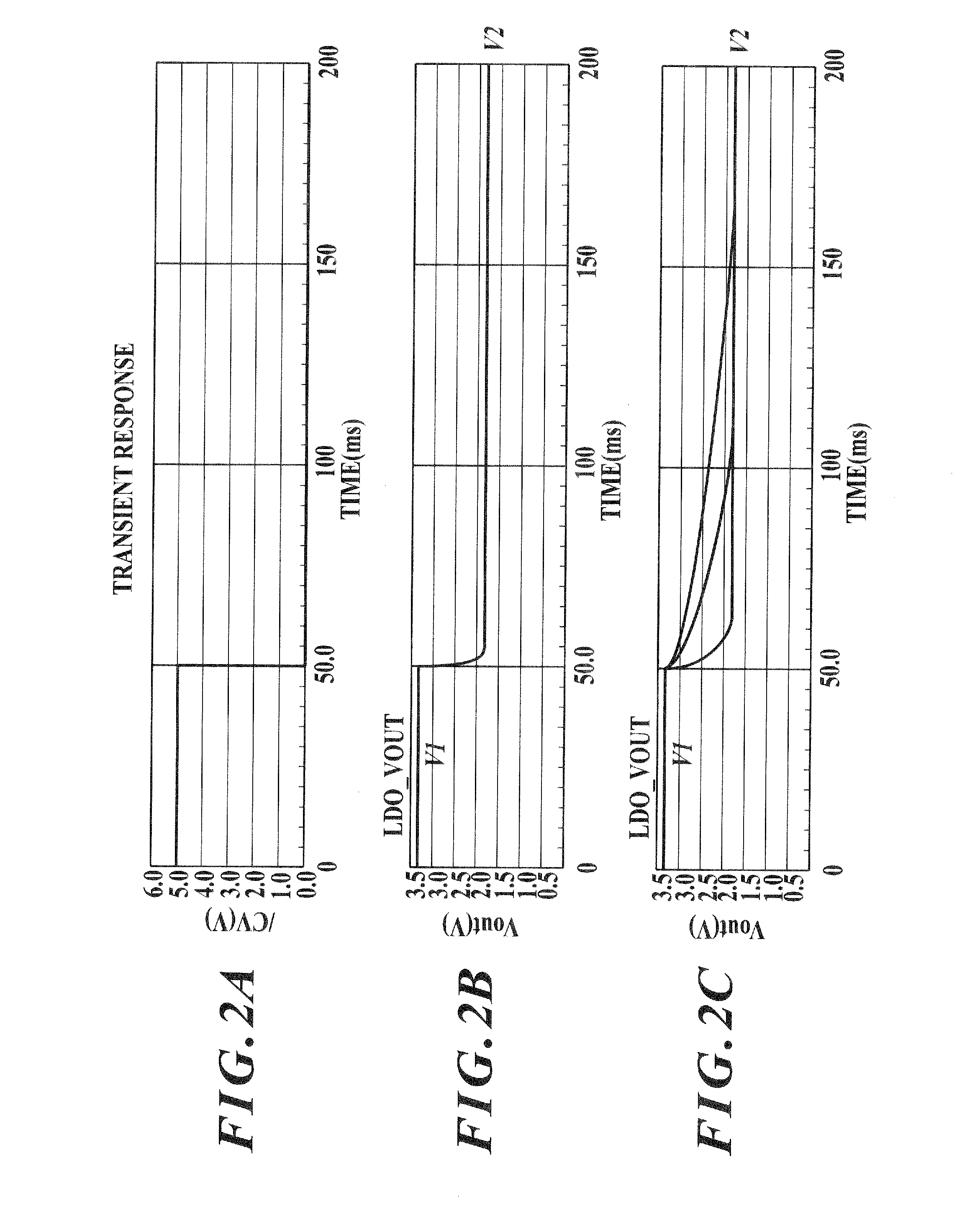
The regulator given the switching function illustrated in FIG. 4, however, allows discharge of an output capacitor Co only through the load, so that it takes a long time to bring the output voltage Vout from a high level down to a low level, proving poor switching response characteristics.
In addition, since current constantly flows through the resistor Ro in the general operation, so that wasteful current will increase.

Method used


Image

  • Semiconductor integrated circuit for regulator
  • Semiconductor integrated circuit for regulator
  • Semiconductor integrated circuit for regulator

Examples


Embodiment Construction

[0020]Preferred embodiments of the present invention will be explained below, referring to the attached drawings.

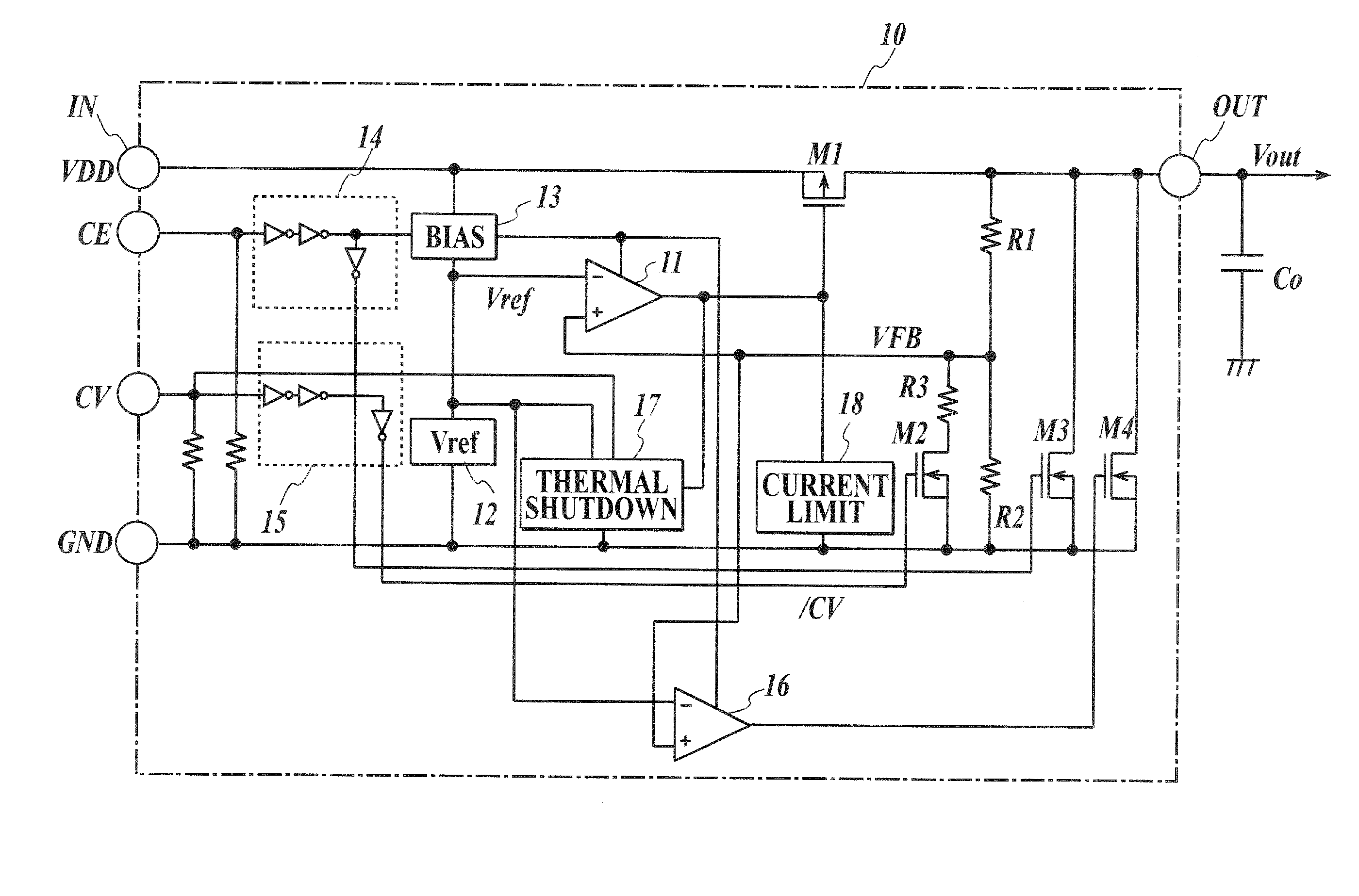
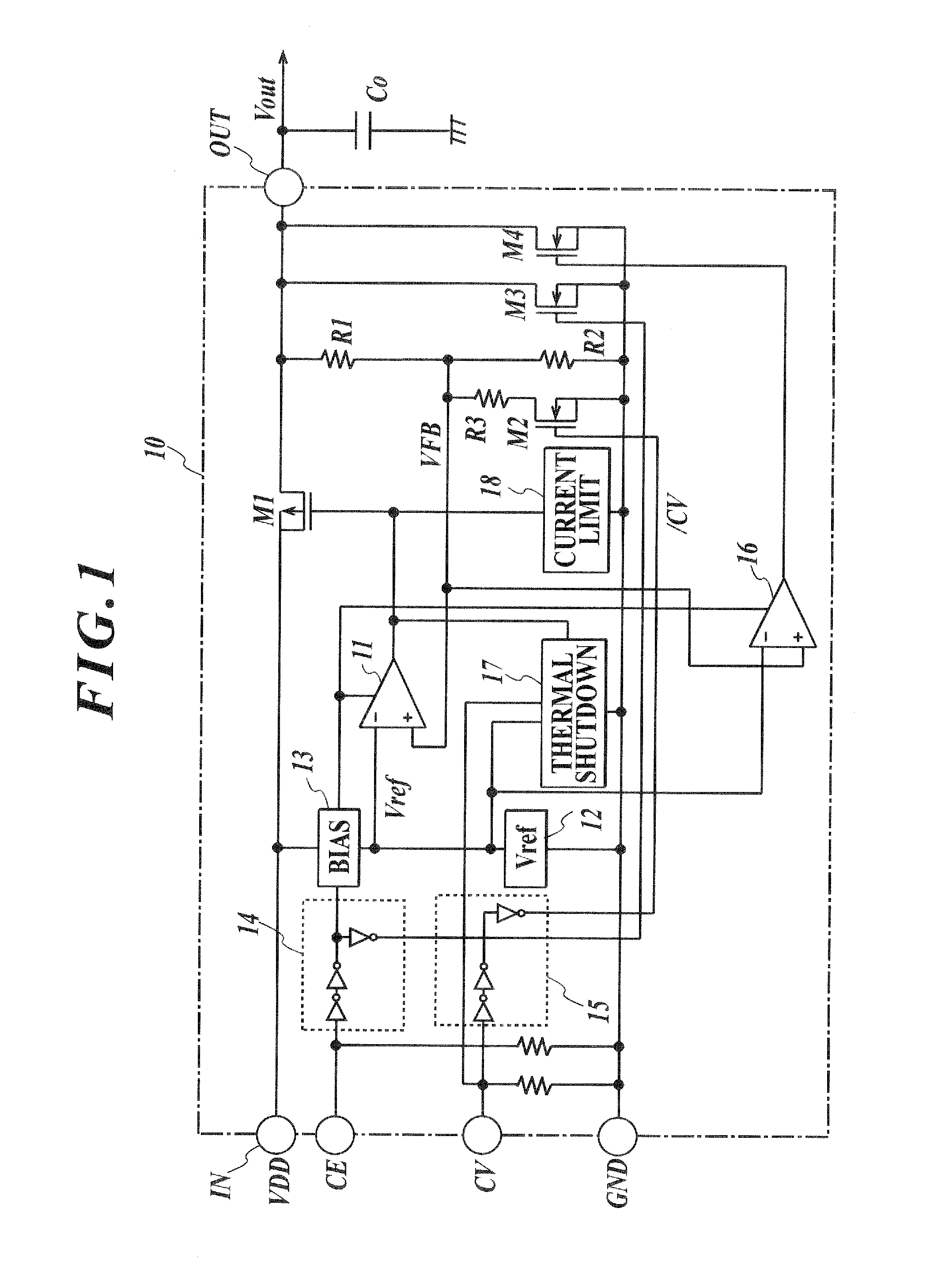
[0021]FIG. 1 illustrates one embodiment of a series regulator (including LDO) applied by the present invention. Although not specifically limited, elements composing a circuit surrounded by a one-dot chain line in FIG. 1 are formed on a single semiconductor chip, so as to configure a semiconductor integrated circuit 10 for controlling the regulator (referred to as regulator IC, hereinafter).

[0022]The regulator IC 10 of this embodiment has a voltage input terminal IN, an output terminal OUT, a voltage control transistor M1, bleeder resistors R1, R2, a resistor R3, a MOS transistor M2, an error amplifier 11, a reference voltage circuit 12, a bias circuit 13, a starting control circuit 14, and a logic circuit 15.

[0023]The voltage input terminal IN is applied with DC voltage VDD from an unillustrated DC voltage source. The voltage control transistor M1 is connected between th...


PUM


Abstract

Disclosed is a semiconductor integrated circuit for regulator including: a control transistor; a voltage divider circuit generating a feedback voltage proportional to an output voltage; a control circuit controlling the control transistor based on difference between the feedback voltage and a reference voltage; and a terminal through which an output voltage switching control signal is received, and being configured to switch the output voltage into a first voltage or into a second voltage lower than the first voltage, by varying division ratio in the voltage divider circuit in response to the signal. The semiconductor integrated circuit further includes: a discharging transistor between the output terminal and the ground; and a circuit outputting a signal for keeping the discharging transistor turned on over a period from change of the signal to fall of the output voltage from the first voltage down to the second voltage.

Description

CROSS-REFERENCE TO RELATED APPLICATION[0001]The present U.S. patent application claims a priority under the Paris Convention of Japanese patent application No. 2011-143659 filed on Jun. 29, 2011, which shall be a basis of correction of an incorrect translation, and is incorporated by reference herein.BACKGROUND OF THE INVENTION[0002]1. Field of the Invention[0003]The present invention relates to a DC power supply and further relates to a voltage regulator which converts DC voltage, and more specifically to a technique effectively applicable to a semiconductor integrated circuit (regulator IC) which configures a series regulator (including low-dropout regulator (LDO)) having an output voltage switching function.[0004]2. Description of Related Art[0005]In DC power supply, there is a demand of switching of output voltage level, for the purpose of suppressing degradation in characteristics of a device which serves as a load to be supplied with electric power. One known control semicondu...

Claims


Application Information

Patent Timeline
Patent Type & Authority Applications(United States)
IPC IPC(8): G05F1/46
CPCG05F1/56
Inventor TERADA, AKIHIRO
Owner MITSUMI ELECTRIC CO LTD
Why Eureka
Eureka Blog
Learn More